9-3 ROTOR
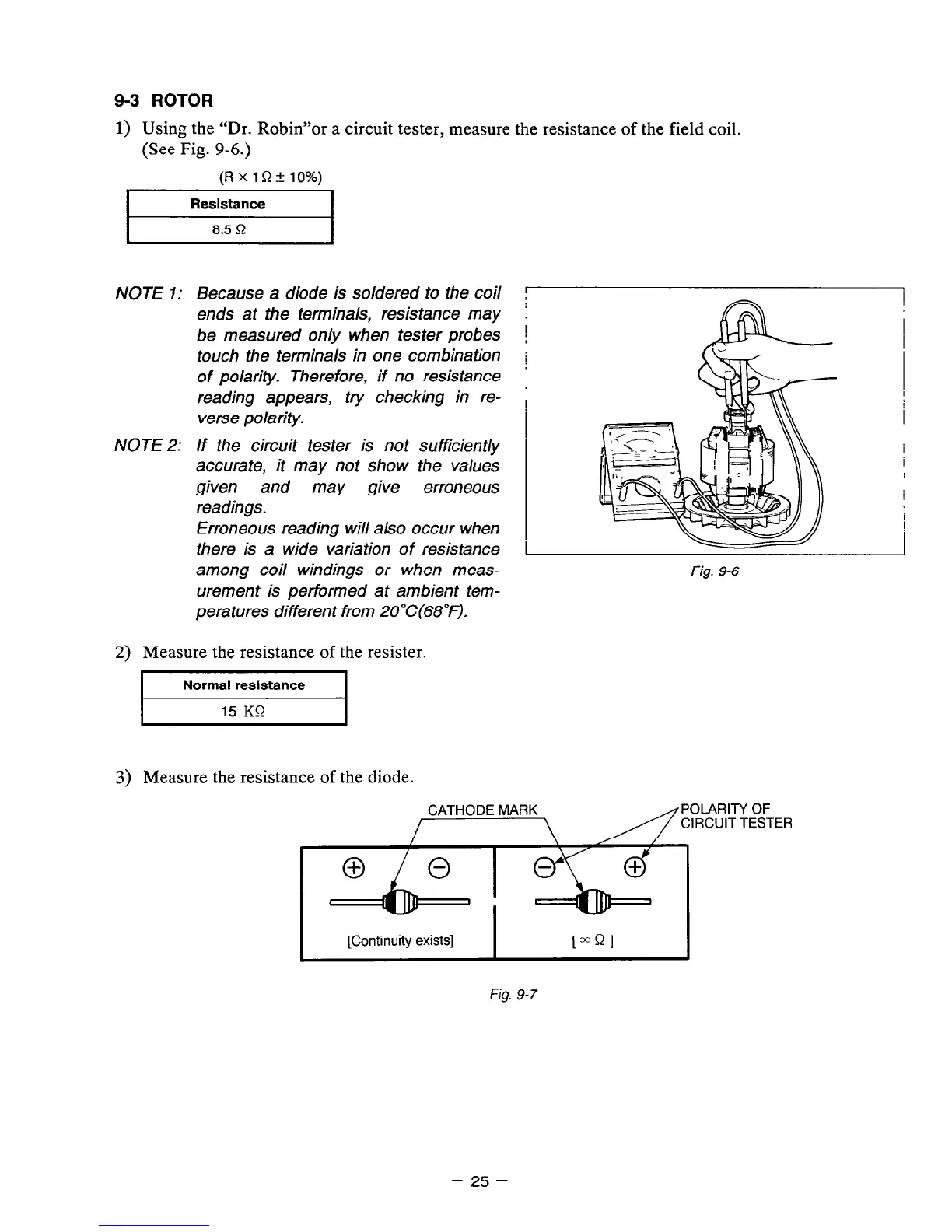
1) Using the “Dr. Robin”or a circuit tester, measure the resistance of the field coil.
(See Fig. 9-6.)
(RxlQ+lo%)
I
Resistance
I
I
8.5 Q
I
NOTE 7: Because a diode is soldered to the coil
ends at the terminals, resistance may
;
be measured on/y when tester probes i
touch the terminals in one combination
of polarity. Therefore, if no resistance
i
reading appears,
try checking in re-
verse polarity.
NOTE 2: If the circuit tester is not sufficiently
accurate, it may not show the values
given
and may give erroneous
readings.
Erroneous reading will also occur when
there is a wide variation of resistance
among coil windings or when meas-
urement is performed at ambient tem-
pera tures different from 20°C(68”F).
Fig. 9-6
2) Measure the resistance of the resister.
I
Normal resistance
I
3) Measure the resistance of the diode.
CATHODE MARK
POLARITY OF
CIRCUIT TESTER
I
[Continuity exists]
I
[“Ql
Fig. 9-7
- 25 -