10-2 DISASSEMBLY PROCEDURES
tep Part to remove
Description
Remarks
Tool
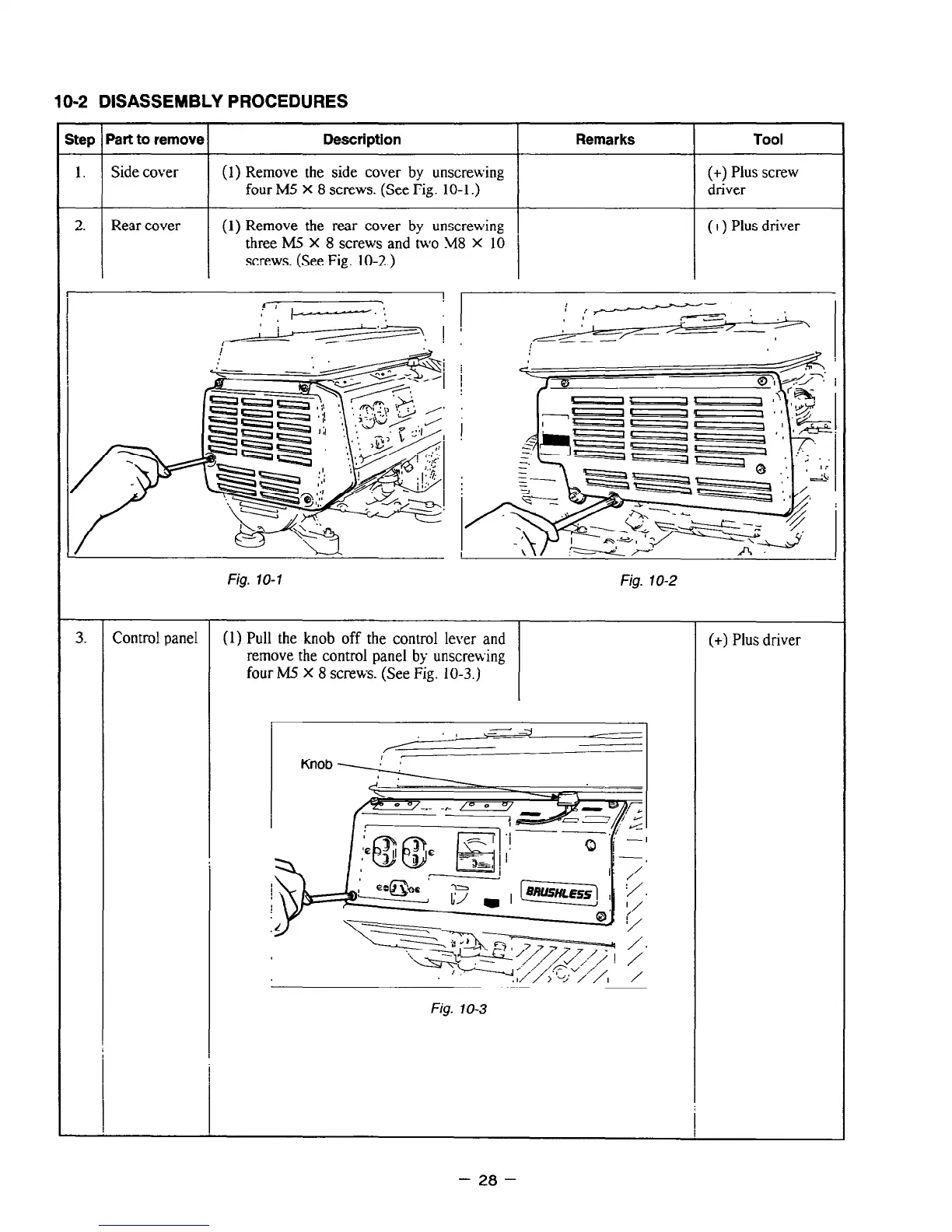
1.
Side cover
(1) Remove the side cover by unscre\xing
(+) Plus screw
four M5 X 8 screws. (See Fig. 10-l.)
driver
2.
Rear cover (1) Remove the rear cover by unscrewing
(+) Plus driver
three M5 X 8 screws and two M8 X 10 ’
screws. (See Fig. 10-2.)
-
3. Control panel
Fig. lo-2
(1) Pull the knob off the control lever and
remove the control panel by unscrewing
four M.5 X 8 screws. (See Fig. 10-3.)
. . _,,,
Fig. IO-3
(+) Plus driver
- 28 -