step
4.
I
t
I
‘art to remove 1
Description
I
Remarks
I
Tool
Couplers
and plugs
(Discon-
nection)
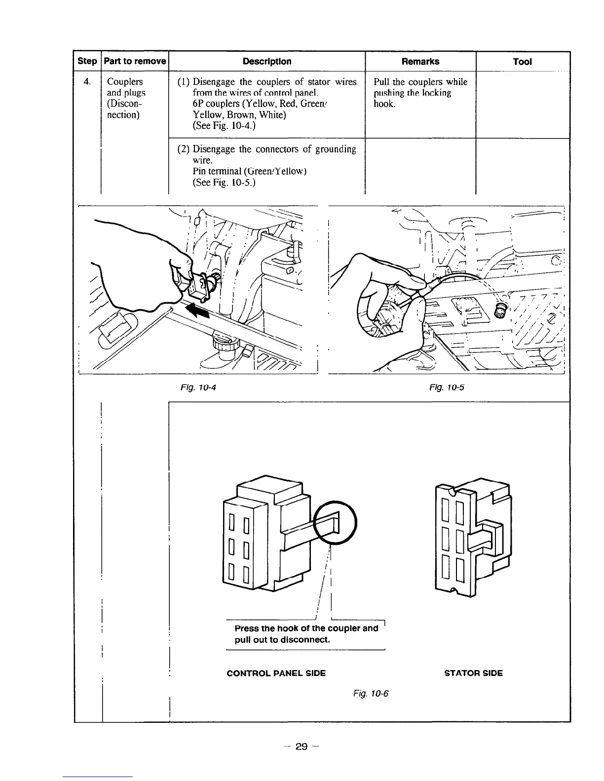
(1) Disengage the couplers of stator wires
from the wires of control panel.
6P couplers (Yellow, Red, Green:
Yellow, Brown, White)
(See Fig. 10-4.)
(2) Disengage the connector of grounding
wire.
Pin terminal (GreenA’ellow)
(See Fig. 10-T)
Pull the couplers while
pushing the locking
hook.
Fig. 10-4
Fig. 10-5
Press the hook of the coupler and
’
pull out to disconnect.
CONTROL PANEL SIDE
STATOR SIDE
I
Fig. IO-6
I
- 29 -