9. CHECKING FUNCTIONAL MEMBERS
9-l CONTROL PANEL
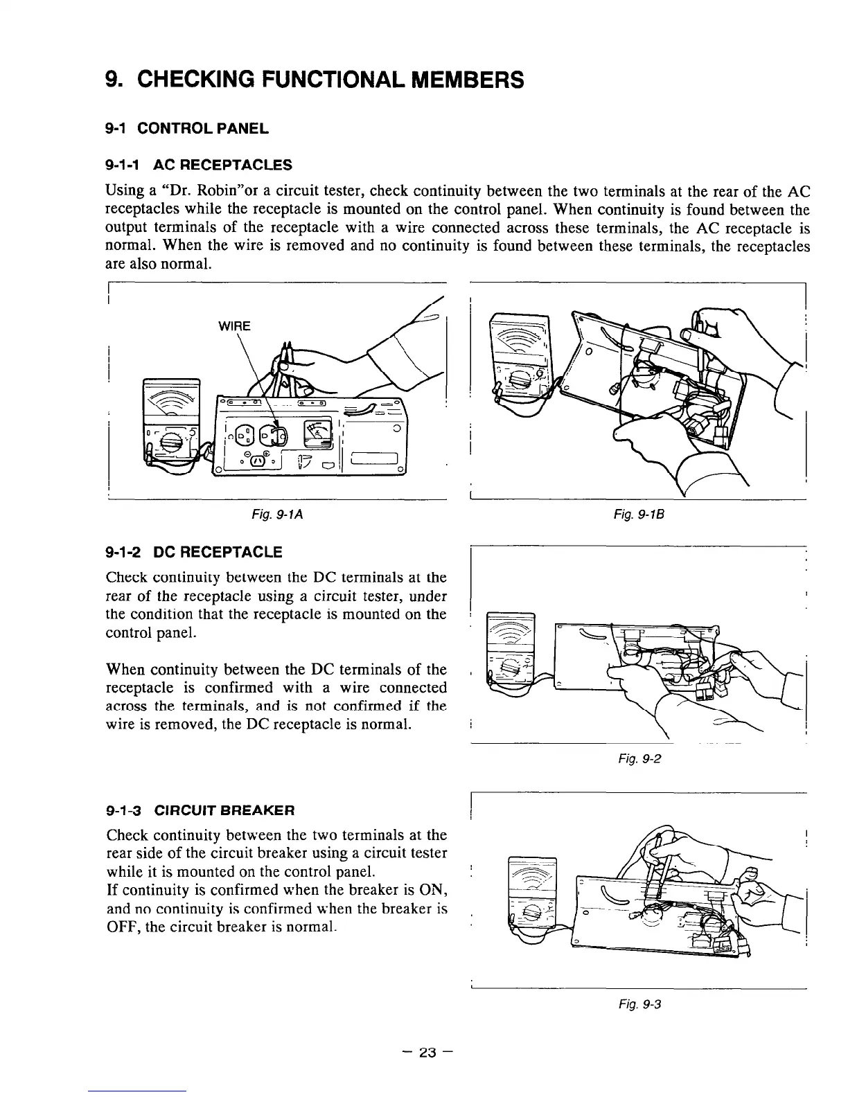
9-1-1 AC RECEPTACLES
Using a “Dr. Robin”or a circuit tester, check continuity between the two terminals at the rear of the AC
receptacles while the receptacle is mounted on the control panel. When continuity is found between the
output terminals of the receptacle with a wire connected across these terminals, the AC receptacle is
normal. When the wire is removed and no continuity is found between these terminals, the receptacles
are also normal.
WIRE
Fig. 9- 1A
9-l-2 DC RECEPTACLE
Check continuity between the DC terminals at the
rear of the receptacle using a circuit tester, under
the condition that the receptacle is mounted on the
control panel.
When continuity between the DC terminals of the
receptacle is confirmed with a wire connected
across the terminals, and is not confirmed if the
wire is removed, the DC receptacle is normal.
Fig. 9-16
Fig. 9-2
9-l-3 CIRCUIT BREAKER
Check continuity between the two terminals at the
rear side of the circuit breaker using a circuit tester
while it is mounted on the control panel.
If continuity is confirmed when the breaker is ON,
and no continuity is confirmed when the breaker is
OFF, the circuit breaker is normal.
Fig. 9-3
- 23 -