9.
CHECKING
FUNCTIONAL
MEMBERS
9-1
VOLTMETER
Check the voltmeter
if
it
is turned on by applying
specific voltage. Voltmeter cannot be checked with
circuit tester because its resistance is too large.
3
Check that no disconnection nor short-circuit
occurs with
a
tester, and the internal resistance
is around
OOk
ohms normally.
3
Turn on the commercial power supply-input
and check the indication.
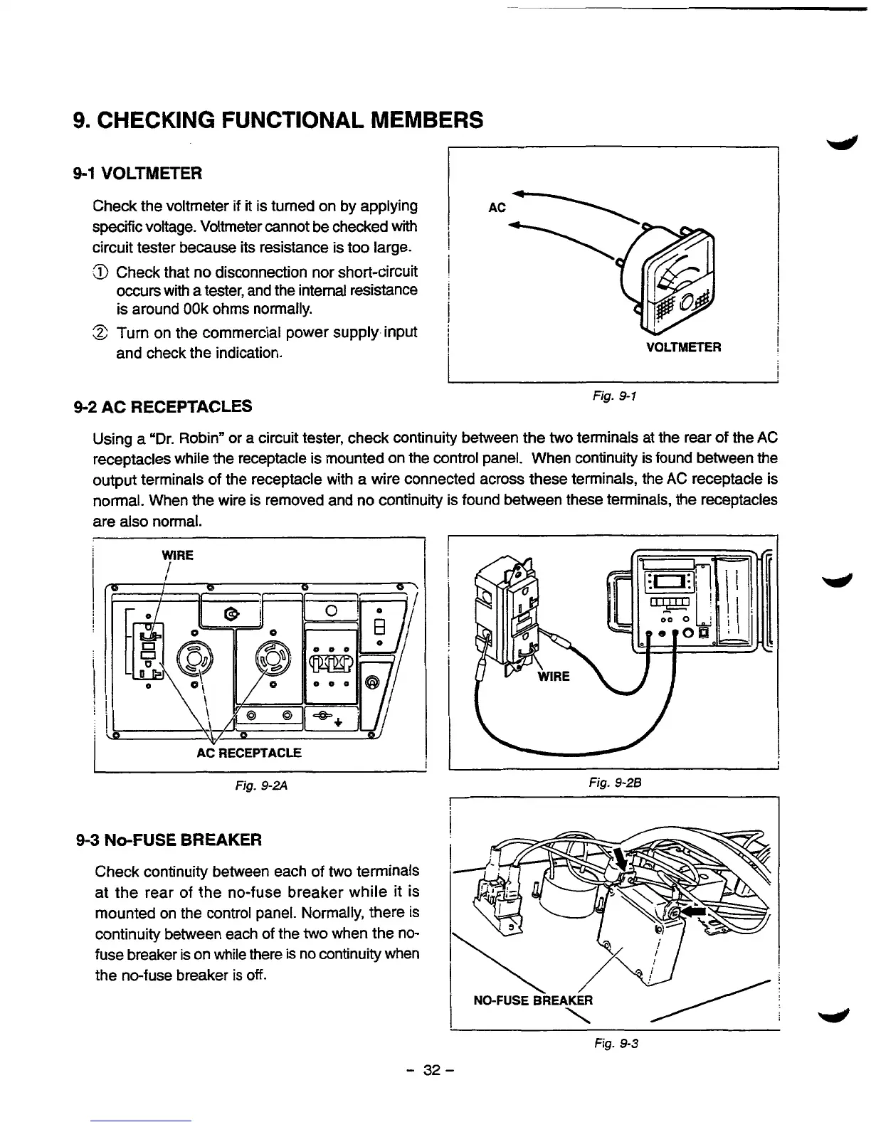
9-2
AC RECEPTACLES
VOLTMETER
Fig.
9-1
Using
a
"Dr. Robin" or a circuit tester, check continuity between the two terminals at the rear of the
AC
receptacles while the receptacle is mounted on the control panel. When continuity is found between the
output terminals
of
the receptacle with a wire connected across these terminals, the AC receptacle is
normal. When the wire is removed and no continuity is found between these terminals, the receptacles
are
also
normal.
It
WIRE
i
AC RECEPTACLE
9-3
NO-FUSE
BREAKER
Fig.
9-2A
Fig.
9-28
1
Check continuity between each
of
two
terminals
at the rear of the no-fuse breaker while it is
mounted on the control panel. Normally, there
is
continuity between each of the
two
when the no-
fuse breaker is on while there
is
no continuity when
the no-fuse breaker
is
off.
\
I
i
NO-FUSE BREAKER
\
Fig.
9-3
-
32-

 Loading...


