Checkina table
for
diaital
circuit
tester.
~~ ~ ~~~~ ~ ~ ~ ~~
Apply
red (plus) needle
of
the
circuit tester
~~ ~~
w
Digital circuit tester
Brown Brown
Brown
/
White
Orange
I
~ ~
Brown
Continuity Continuity Orange
Continuity
No
continuity
-
No
continuity Brown
Continuity
No
continuity
No
continuity
-
-
Continuity
Apply
black
(minus) needle
of
the
circuit tester
Brown /White
-
No
continuity
No
continuity
No
continuity
NOTE
1
:
Because of the difference of measuring method between the analogue circuit tester and the
digital circuit tester, polar@ of tester needles should be reversed.
NOTE
2
:
"Continuit)r means forward direction characteristics of the diode, and different from short
circuit condition (in which a pointer of the tester goes
out
of its normal scale), shows resistance
to some extent. When results of the checking indicates failure even in one section, replace
with a new one.
NOTE
3
:
Simpson brand analogue testers have the characteristics as same as the digital circuit testeL
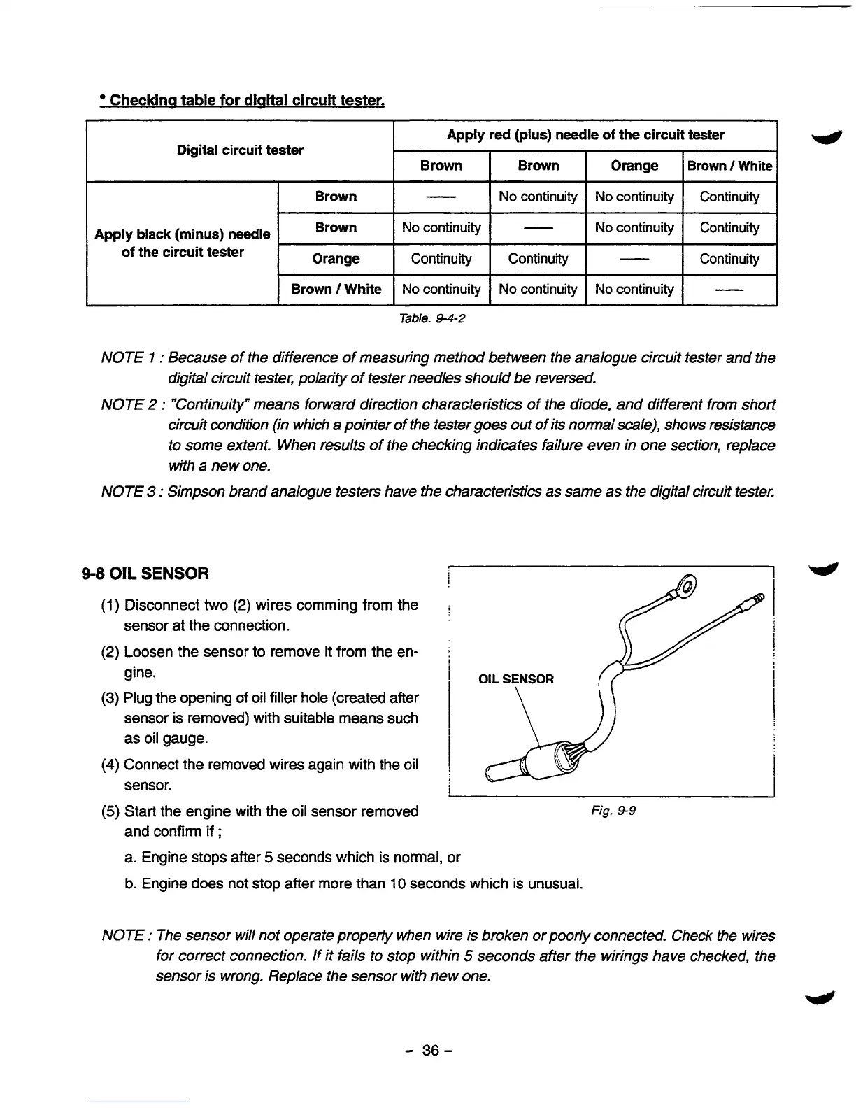
9-8
OIL
SENSOR
j
~4
(1)
Disconnect
two
(2)
wires comming from the
(2)
Loosen gine. the sensor to remove it from the en-
:
i
pi
i
sensor at the connection.
i
OIL
SENSOR
I
(3)
Plug the opening
of
oil filler hole (created after
sensor is removed) with suitable means such
I
as oil gauge.
(4)
Connect the removed wires again with the oil
,
sensor.
i
(5)
Start the engine with the
oil
sensor removed
Fig.
9-9
and confirm
if
;
a.
Engine stops after
5
seconds which is normal, or
b.
Engine does not
stop
after more than
10
seconds which is unusual.
NOTE
:
The sensor will not operate properly when wire is broken or poorly connected. Check the wires
for correct connection. If it fails to stop within
5
seconds after the wirings have checked, the
sensor is wrong. Replace the sensor with new one.
4
-
36-
 Loading...


