9-5
ROTOR
ASSEMBLY
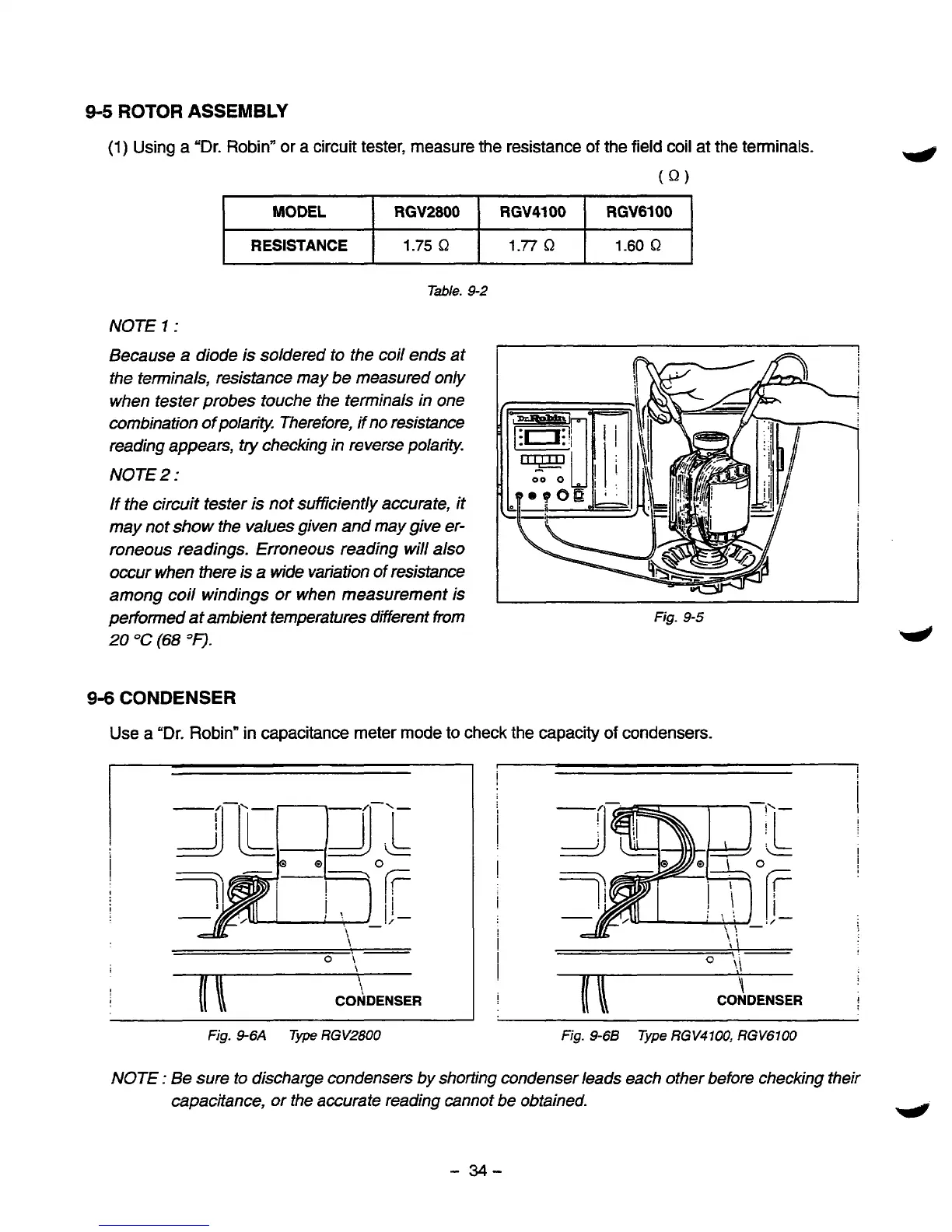
(1)
Using a "Dr. Robin" or a circuit tester, measure the resistance
of
the field coil at the terminals.
(Q)
MODEL
RGV6100 RGV4100
RGV2800
RESISTANCE
1.60
Q
1.77
a
1.75
Q
Table.
9-2
NOTE
7
:
Because a diode is soldered
to
the coil ends at
the terminals, resistance may be measured only
when tester probes touche the terminals in one
combination
of
polarity. Therefore, if no resistance
reading appears,
try
checking in reverse polarity.
NOTE
2
:
If
the
circuit tester is not suff7ciently accurate, it
may not show the values given and may give er-
roneous readings. Erroneous reading will
also
occur when there
is
a wide variation
of
resistance
among coil windings or when measurement is
performed
at
ambient temperatures different from
20
"C
(68
=F).
9-6
CONDENSER
Fig-
9-5
Use
a
"Dr.
Robin" in capacitance meter mode to check the capacity
of
condensers.
\
(I
\
!
CONDENSER
I
1:
!
i
I
!
i
I
I
\
CONDENSER
Fig.
46A
Type
RGV2800
Fig.
9-6B
Type
RGV4700,
RGV6100
NOTE
:
Be sure
to
discharge condensers by shorting condenser leads each other before checking their
capacitance, or the accurate reading cannot be obtained.
-
34-

 Loading...


