NORMAL CAPACITY
OF
CONDENSER
RGV2800 RGV4100 RGV6100
20pFx2 28pFx2
Table.
9-3
If
such an instrument
is
unavailable, the condenser can be checked
by
replacing with a new one. If the
generator performs good with new condenser, the cause of trouble is defect in original condenser.
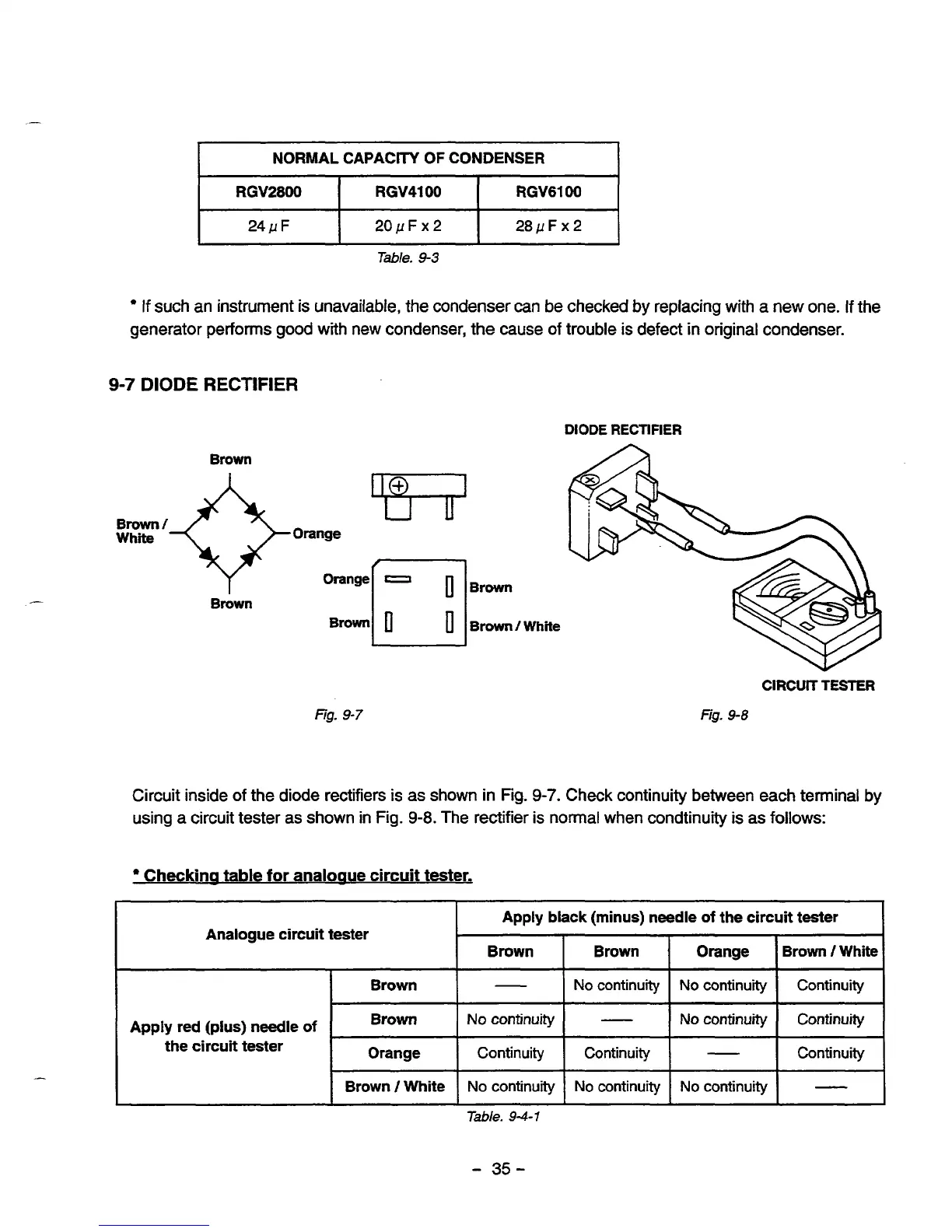
9-7
DIODE
RECTIFIER
DIODE
RECTIFIER
Brown
Brown/
Whim
1
Brown
Brown
/
White
fig.
9-7
CIRCUIT TESTER
Fig.
9-8
Circuit inside of the diode rectifiers is as shown in
Fig.
9-7.
Check continuity between each terminal by
using a circuit tester as shown in Fig.
9-8.
The rectifier is normal when condtinuity is as follows:
Checkina table for analogue circuit tester.
Analogue circuit tester
Apply black (minus) needle
of
the circuit tester
Brown Brown
I
Brown
I
-
I
NO
continuity
I
NO
continuity
I
Continuity
I
Apply red (plus) needle
of
the circuit tester
Brown
Continuity
No
continuity
-
No
continuity
I
Continuity Continuity
Orange
-
Continuity
Brown /White
-
No
continuity
No
continuity
No
continuity
Table.
94-1
-
35-
 Loading...


