Copyright 2021 @ Rockchip Electronics Co., Ltd. 30
CIF_D12/EBC_SDDO12/GMAC1_RXD3_M1
CIF_D10/EBC_SDDO10/GMAC1_TXCLK_M1
CIF_D7/EBC_SDDO7/VOPBT656_D7_M1
CIF_D6/EBC_SDDO6/VOPBT656_D6_M1
CIF_D10/EBC_SDDO10/GMAC1_TXCLK_M1
CIF_D5/EBC_SDDO5/VOPBT656_D5_M1
CIF_D14/EBC_SDDO14/GMAC1_TXD0_M1
CIF_D4/EBC_SDDO4/VOPBT656_D4_M1
CIF_D15/EBC_SDDO15/GMAC1_TXD1_M1
CIF_D8/EBC_SDDO8/GMAC1_TXD2_M1
CIF_D3/EBC_SDDO3//VOPBT656_D3_M1
CIF_D9/EBC_SDDO9/GMAC1_TXD3_M1
CIF_D3/EBC_SDDO3//VOPBT656_D3_M1
CIF_D1/EBC_SDDO1/VOPBT656_D1_M1
CIF_VSYNC/EBC_SDOE/GMAC1_MDIO_M1
CIF_D0/EBC_SDDO0/VOPBT656_D0_M1
CIF_HREF/EBC_SDLE/GMAC1_MDC_M1
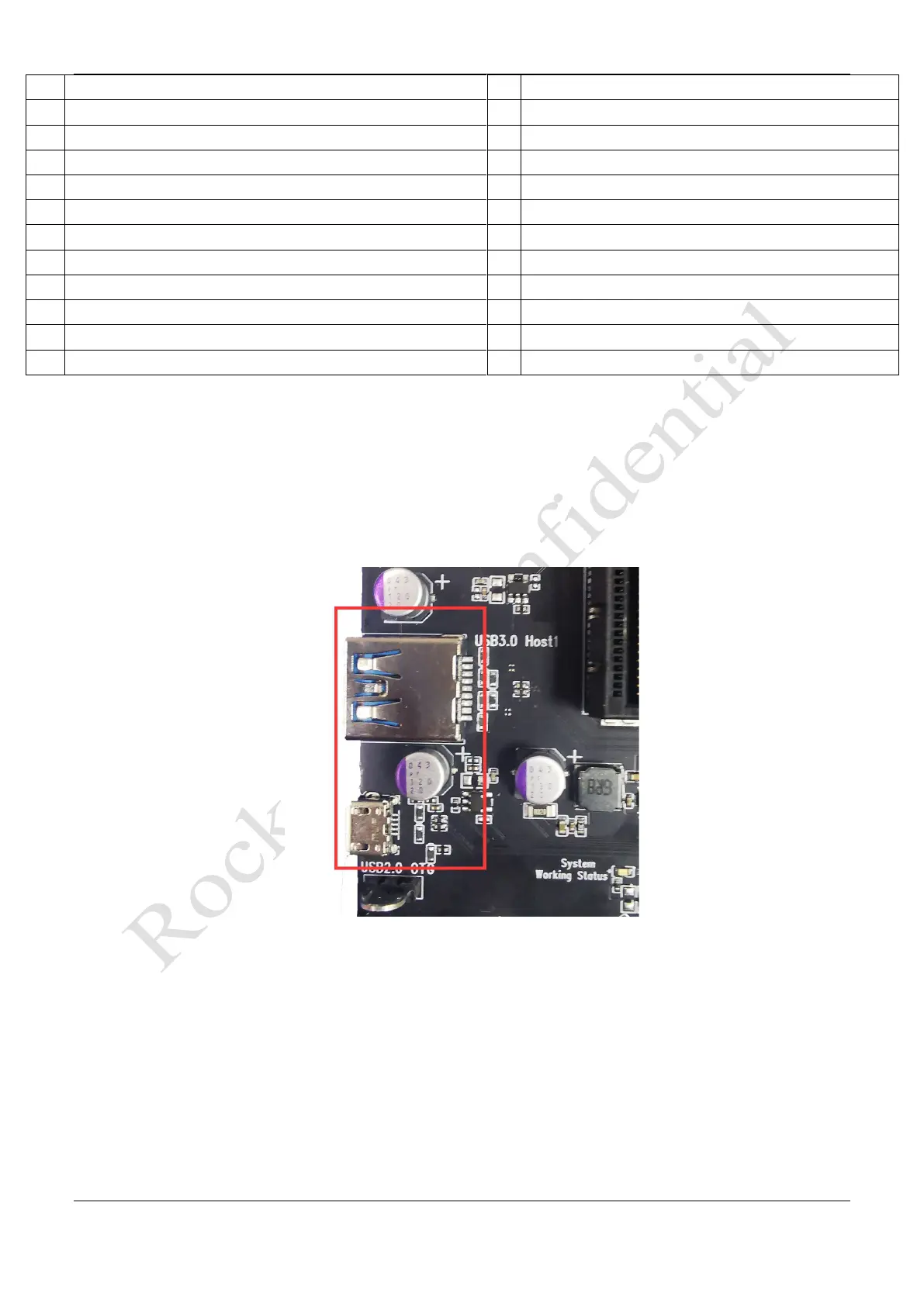
3.18 USB OTG/HOST Interface
The Development board with USB OTG and USB HOST interface:
⚫ USB2.0 OTG uses USB2.0 micro-A interface which can be used to download and upgrade firmware.
⚫ USB3.0 HOST1 uses USB3.0 Standard-A interface and is backward compatible with USB 2.0 specification.
Figure 3-23 Micro USB2.0 OTG and USB3.0 HOST1 Interface
⚫ USB2.0 HOST2/3 takes USB2.0 Standard-A interface, which is convenient to connect USB2.0 peripherals
such as U disk and mouse directly.