284 Rockwell Automation Publication 1766-UM001O-EN-P - September 2021
Appendix G Connect to Networks via Ethernet Interface
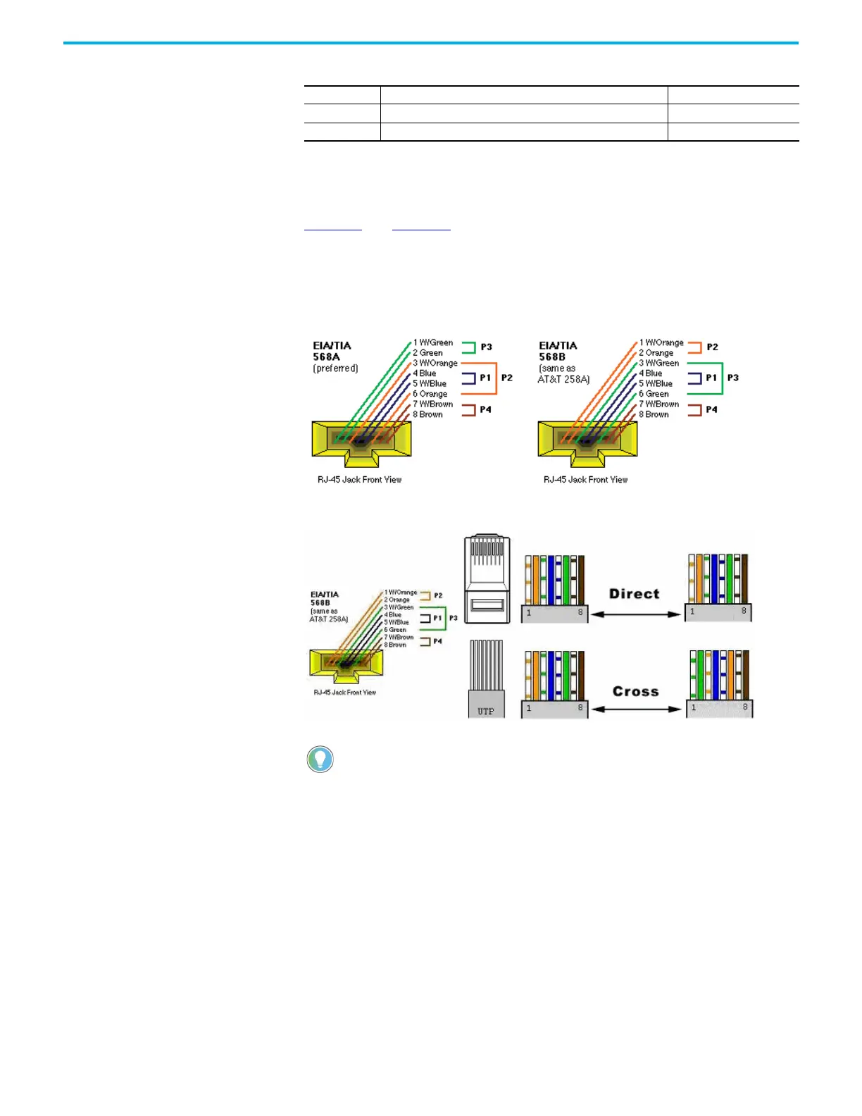
The standard Ethernet cable is terminated in accordance with EIA/TIA 568B on
both ends. The crossover cable is terminated to EIA/TIA 568B at one end and
EIA/TIA 568A at the other, exactly as shown in the two color coded plugs below.
Figure 77
and Figure 78 show how the TIA/EIA 568A and 568B are to be
terminated. There are four pairs of wires contained in a CAT5 UTP cable. These
pairs of cables are color coded white blue/blue, white orange/orange, white
green/green, white brown/brown, they are also numbered one to four in the
order shown.
Figure 77 - EIA/TIA 568A and 568B Ethernet Cable
Figure 78 - EIA/TIA 568A and 568B Termination
6 Rx- Green
7 No used by 10/100Base-T Brown/White
8 No used by 10/100Base-T Brown
The most common wiring for RJ45 cables is the straight through cable which means
that pin 1 of the plug on one end is connected to pin 1 of the plug on the other end. The
straight through RJ45 cable is commonly used to connect network cards with hubs on
10Base-T and 100Base-Tx networks. On network cards, pair 1-2 is the transmitter, and
pair 3-6 is the receiver. The other two pairs are not used. On hubs pair 1-2 is the
receiver and 3-6 the transmitter. It may be best to wire your cables with the same
color sequence. In this cable layout, all pins are wired one-to-one to the other side.
The pins on the RJ45 connector are assigned in pairs, and every pair carries one
differential signal. Each line pair has to be twisted.
In small networks where only two Ethernet devices need to be connected together
point-to-point, a cross over RJ45 cable may be necessary, where the transmit and
receive lines on both JR45 connectors are cross connected. The color coding for the
cross over RJ45 cable have been defined in the EIA/TIA 568A standard. In a cross-over
cable layout, you should remember that one end is normal, and the other end has the
cross-over configuration.
However, because the MicroLogix 1400 Ethernet port implements auto-crossover (also
called Automatic MDI/MDI-X Configuration), a straight through cable may be used even
for direct point-to-point connections between the MicroLogix 1400 and another
Ethernet device.
Table 42 - Straight-through cabling (Continued)
 Loading...


