52 Rockwell Automation Publication 2198-UM005C-EN-P - February 2022
Chapter 4 Connector Data and Feature Descriptions
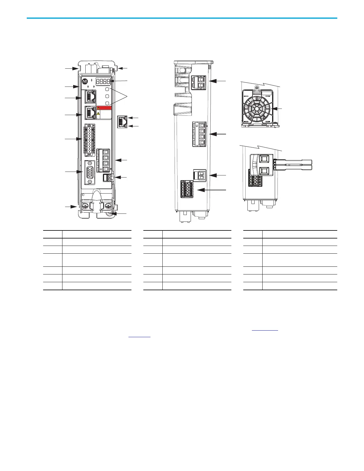
Kinetix 5300 Connector Data Use these illustrations to identify the connectors and indicators for the
Kinetix 5300 drive modules.
Figure 26 - Kinetix 5300 Drive Features and Indicators
Safe Torque Off Connector Pinout
For the hardwired Safe Torque Off (STO) connector pinouts, feature
descriptions, and wiring information, refer to Chapter 9 beginning on
page 159.
Item Description Item Description Item Description
1 Motor cable shield clamp 7 Zero-stack mounting tab/cutout 13 Motor brake connector
2 Motor feedback (MFB) connector 8 Four-character status display 14 Ground terminal
3
Digital inputs and auxiliary feedback
connector
9 Navigation pushbuttons 15 Shunt resistor connector
4 Ethernet (PORT1) RJ45 connector 10 Link speed status indicators 16 AC input power connector
5 Ethernet (PORT2) RJ45 connector 11 Link/Activity status indicators 17 24V control input power connector
6 Module and Network status indicators 12 Motor power connector 18 Safe Torque Off (STO) connector
18
17
16
15
L3
L2
L1
1
8
2
3
11
4
5
9
10
14
6
7
13
12
L3L2
L1
24+
DC+ SH
24-
SB+
SB-
S1
SC
S2
7
SB+
SB-
S1
SC
S2
2
1
2
1
MOD NET
MBRK
W
V
U
1
10
1
2
MFB
SELECT
BACK
NEXT
KINETIX
5300
DANGER
Electric shock
risk. Power
o and wait
5 minutes.
U
V
W
Kinetix 5300 Drive, Front View
(2198-C1004-ERS drive is shown)
Kinetix 5300, Top View
(2198-C1004-ERS drive is shown)
Shared-bus 24V Input
Wiring Connector
Kinetix 5300, Bottom View
(frame 2 and 3 drives only)
Cooling Fan
 Loading...


