64 Rockwell Automation Publication 2198-UM005C-EN-P - February 2022
Chapter 4 Connector Data and Feature Descriptions
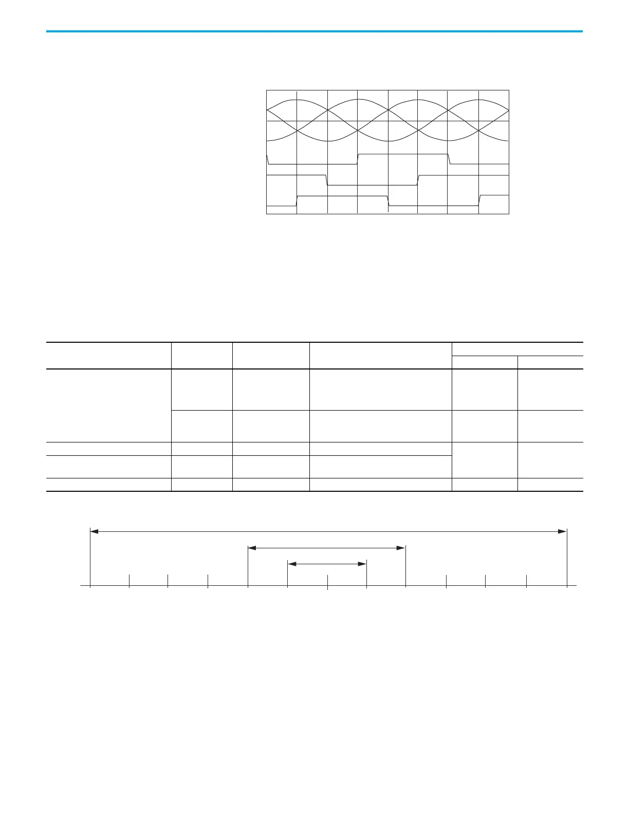
The drive MFB feedback connector uses Hall signals to initialize the
commutation angle for permanent magnet motor commutation.
Figure 32 - Hall Encoder Phasing
Absolute Position Feature
The absolute position feature of the drive tracks the position of the motor,
within the multi-turn retention limits, while the drive is powered off. The
absolute position feature is available with only multi-turn encoders.
Table 33 - Absolute Position Retention Limits
Figure 33 - Absolute Position Limits (measured in turns or revolutions)
V
UN
V
WN
V
VN
S1
S2
S3
300
0
60 120 180 240 300 60
0
Encoder Type
Cat. No.
Designator
Motor Cat. No. Actuator Cat. No.
Retention Limits
Turns (rotary) mm (linear)
Hiperface
-M
MPL-A/Bxxxxx-M
MPM-A/Bxxxxx-M
MPF-A/Bxxxxx-M
MPS-A/Bxxxxx-M
MPAR-A/B3xxxx-M
MPAI-A/BxxxxxM
2048 (±1024) –
-V MPL-A/Bxxxxx-V
MPAS-A/Bxxxx1-V05, MPAS-A/Bxxxx2-V20
MPAR-A/B1xxxx-V, MPAR-A/B2xxxx-V
MPAI-A/BxxxxxV
4096 (±2048) –
Nikon (24-bit) serial with battery backup -D TLP-A/Bxxxx-D –
65,536 (±32,768) –
Tamagawa (17-bit) serial with battery
backup
-B
TL-Axxxx-B
TLY-Axxxx-B
–
Hiperface (magnetic scale) -xDx –LDAT-Sxxxxxx-xDx – 960 (37.8)
+2048-2048 +1024-1024
-16,384 -8192
0
-32,768
-4096
+16,384+8192
+32,768
+4096
Position at Power Down
65,536 Revolutions
4096 Turns
2048 Turns
 Loading...


