Rockwell Automation Publication 2198-UM005C-EN-P - February 2022 171
Appendix A Interconnect Diagrams
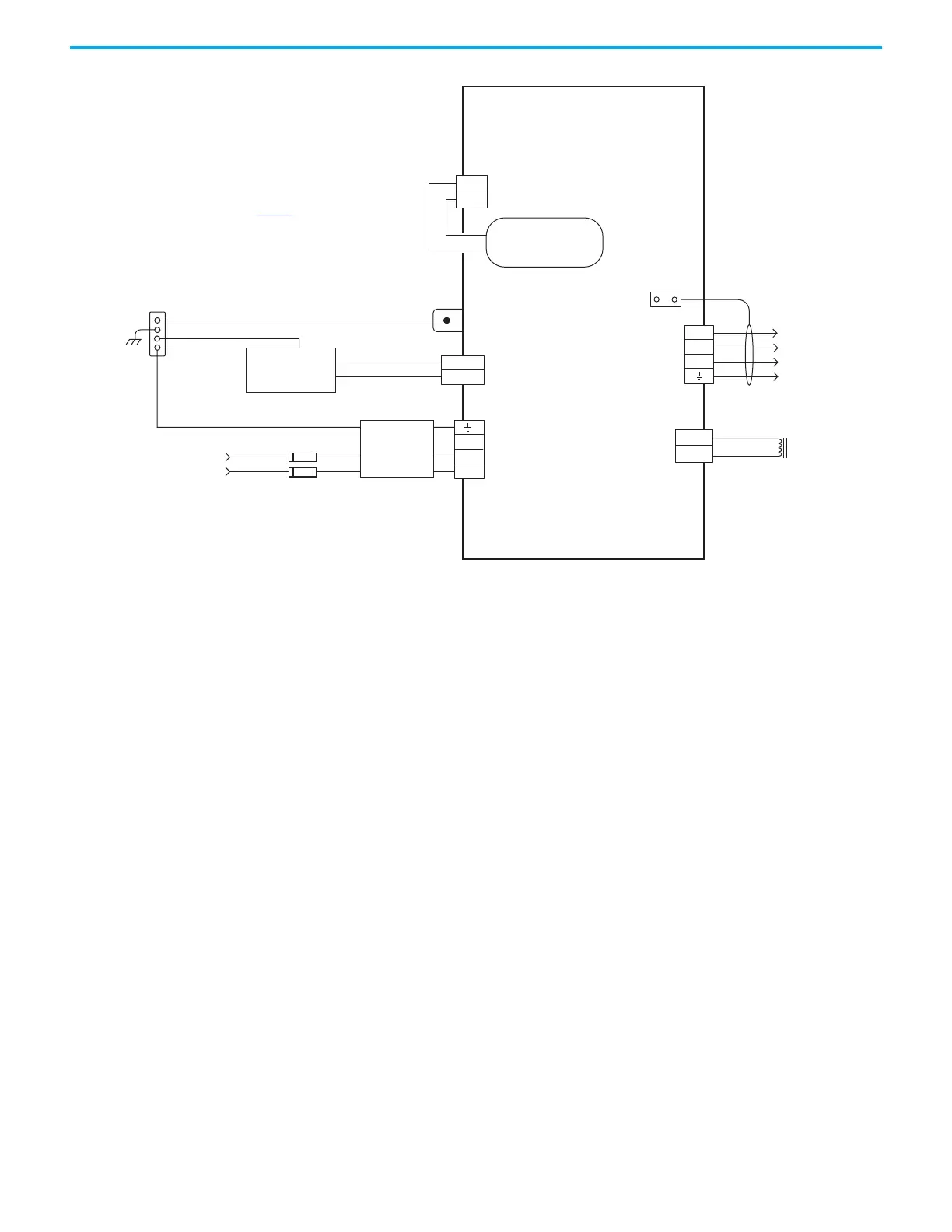
Figure 80 - Kinetix 5300 Drives Power Wiring (single-phase operation)
L3
L2
L1
2
1
MBRK -
MBRK +
U
V
W
2
1
4
3
2
1
4
3
2
1
MBRK -
MBRK +
DC+
SH
24V–
24V+
85…132V AC rms
or 170…253V AC rms
Single-phase Input
Bonded Cabinet Ground Bus
Control Power
AC Input Power
Connector
* Indicates Customer Supplied Component
2198-C1004-ERS, 2198-C1007-ERS,
2198-C1015-ERS, 2198-C1020-ERS
Kinetix 5300 Drives
Chassis
Note 4
Customer Supplied
+24V DC
Power Supply *
Motor Brake
Three-phase
Motor Power
Connections
Note 8
Motor Power
Cable Shield
Refer to table on page 169
for note information.
Shunt
Motor Brake
Connections
Circuit Protection *
Note 2
2198-DBxxx-F
Three-phase
AC Line Filter
Internal Shunt
Note 7
PE Ground
Note 5
 Loading...


