10 Rockwell Automation Publication 2198-IN001D-EN-P - February 2016
Kinetix 5500 Servo Drives
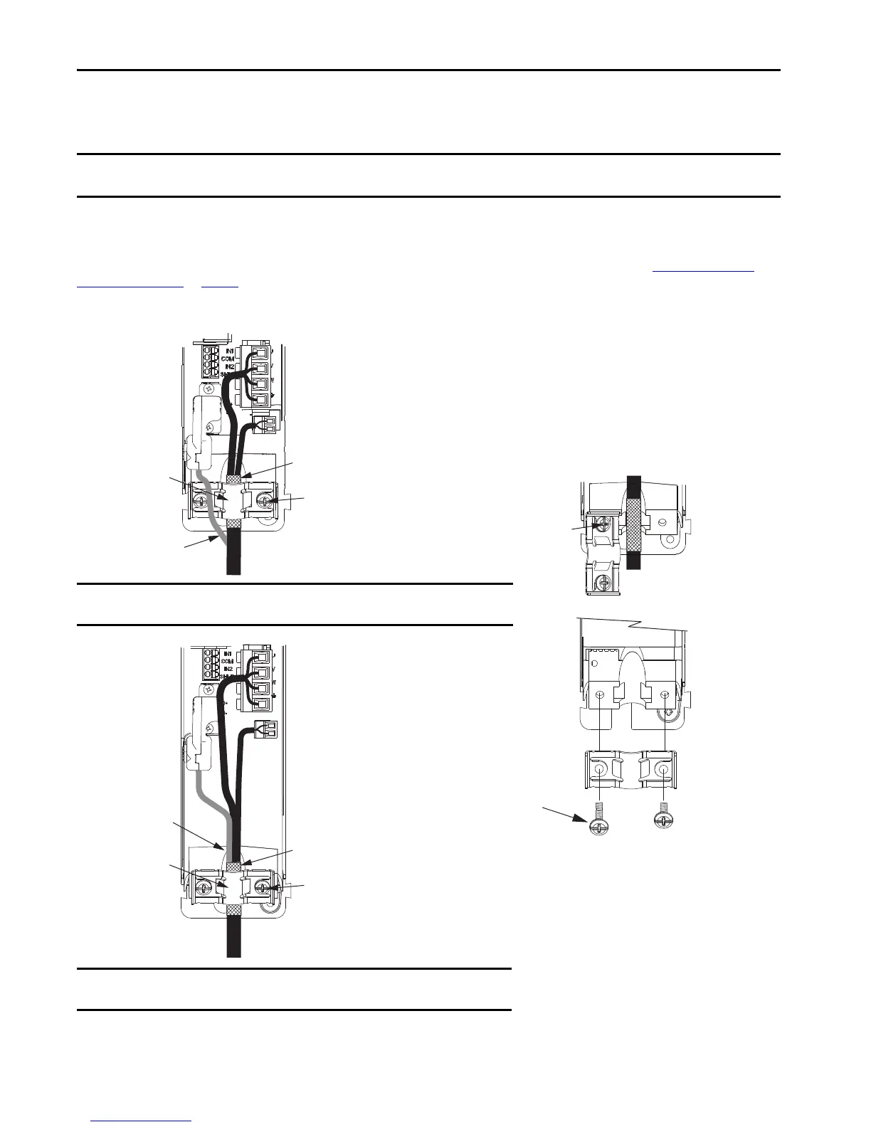
Attach the Motor Cable Shield Clamp
A shield clamp and two screws are supplied with each Kinetix 5500 drive. Use the clamp to bond the motor cable shield-braid to chassis ground.
Kinetix VP Servo Motors
These examples illustrate 2090-CSxM1DF/DG motor cables with connections to Kinetix VP motors and using 2198-KITCON-DSL feedback
connector kits. If your motor connections are coming from other compatible Allen-Bradley® servo motors/actuators, see Other Allen-Bradley
Motors and Actuators on page 11.
Cable Shield Clamp Installation
IMPORTANT • Loosen the retention screw, if needed, until you can start threading both clamp screws with the cable shield under the clamp.
• Make sure the cable clamp tightens around the cable shield and provides a good bond between the cable shield and the drive chassis.
Motor Cable
Shield Clamp
2198-KITCON-DSL
Motor Feedback
Connector Kit
Motor Power
(MP) Connector
Motor Brake
(BC) Connector
Exposed shield braid
under clamp.
Feedback cable routed
around the shield clamp.
Shield Clamp Screws (2)
2.0 N•m (17.7 lb•in), max
Kinetix 5500 Servo Drives,
Frame 1 or 2, Front View
(frame 1 is shown)
2090-CSBM1DF-18AAxx
Single Motor Cable
Clamp features apply
to all frame sizes.
Servo Drive
Shield Clamp
Retention Screw
Motor Cable
Shield Clamp
Motor Power
(MP) Connector
Motor Brake
(BC) Connector
Exposed shield braid
under clamp.
Shield Clamp Screws (2)
Feedback cable routed
within the shield braid.
2198-KITCON-DSL
Motor Feedback
Connector Kit
Kinetix 5500 Servo Drives,
Frame 2 or 3, Front View
(frame 2 is shown)
2090-CSBM1DF-14AAxx
Single Motor Cable
Servo Drive
Retention Screw
(loosen, do not remove)
IMPORTANT When the drive/motor combination calls for 18 AWG cable, the feedback cable routes
around the motor cable shield clamp.
IMPORTANT When the drive/motor combination calls for 14 or 10 AWG cable, the feedback cable
routes along with the power and brake wiring.

 Loading...


