14 Rockwell Automation Publication 2198-IN001D-EN-P - February 2016
Kinetix 5500 Servo Drives
Shared AC/DC and Hybrid Systems
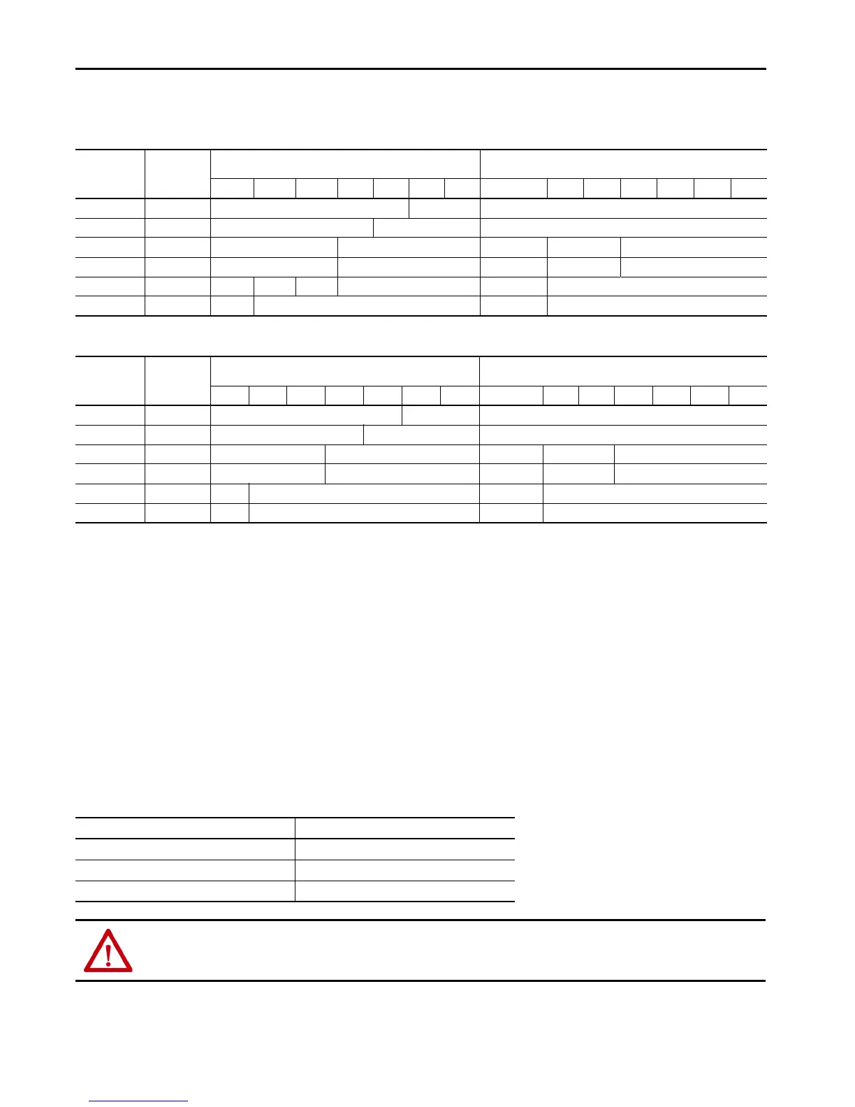
Input Power UL Circuit-protection Specifications
Input Power IEC (non-UL) Circuit-protection Specifications
Motor Overload Protection
This servo drive uses solid-state motor overload protection that operates in accordance with UL requirements. Motor overload protection is
provided by algorithms (thermal memory) that predict actual motor temperature that is based on operating conditions.
In addition to thermal memory protection, this drive provides an input for an external temperature sensor/thermistor device, embedded in the
motor, to support the UL requirement for motor overload protection.
Servo drives using DSL (digital servo link) encoder technology require the encoder to perform motor temperature monitoring and transmit the
data over the single motor cable. Kinetix VP motors use DSL technology that performs this function. No additional wiring is required.
Some motors supported by this drive (firmware revision 3.001 or earlier) do not contain temperature sensors/thermistors; therefore, motor
overload protection against excessive consecutive motor overloads with power cycling is not supported. Beginning with firmware revision 4.001
(and later) thermal retention is supported regardless of the motor or encoder type in use.
This servo drive meets the following UL requirements for solid-state overload protection.
Refer to your servo drive user manual for the interconnect diagram that illustrates the wiring between your motor and drive.
Kinetix 5500
Drive Cat. No.
Drive Voltage,
(three-phase)
nom
Bussmann Fuse
Cat. No.
Molded Case CB
Cat. No.
2 Axes 3 Axes 4 Axes 5 Axes 6 Axes 7 Axes 8 Axes 2 Axes 3 Axes 4 Axes 5 Axes 6 Axes 7 Axes 8 Axes
2198-H003-ERSx 240/480V KTK-R-10 KTK-R-15 N/A
2198-H008-ERSx 240/480V KTK-R-15 KTK-R-20 N/A
2198-H015-ERSx 240/480V KTK-R-20 N/A 140U-D6D3-C15 140U-D6D3-C20 N/A
2198-H025-ERSx 240/480V KTK-R-30 N/A 140U-D6D3-C20 140U-D6D3-C30 N/A
2198-H040-ERSx 240/480V KTK-R-30 LPJ-45SP LPJ-50SP N/A 140U-D6D3-C30 N/A
2198-H070-ERSx 240/480V LPJ-50SP N/A 140G-G6C3-C50 N/A
Kinetix 5500
Drives Cat. No.
Drive Voltage,
(three-phase)
nom
DIN gG Fuses
Amps (max)
Molded Case CB
Cat. No.
2 Axes 3 Axes 4 Axes 5 Axes 6 Axes 7 Axes 8 Axes 2 Axes 3 Axes 4 Axes 5 Axes 6 Axes 7 Axes 8 Axes
2198-H003-ERSx 240/480V 10 16 N/A
2198-H008-ERSx 240/480V 16 N/A N/A
2198-H015-ERSx 240/480V 20 N/A 140U-D6D3-C15 140U-D6D3-C20 N/A
2198-H025-ERSx 240/480V 32 N/A 140U-D6D3-C20 140U-D6D3-C30 N/A
2198-H040-ERSx 240/480V 32 N/A 140U-D6D3-C30 N/A
2198-H070-ERSx 240/480V 50 N/A 140G-G6C3-C50 N/A
Motor Overload Protection Trip Point Value
Ultimately 100% overload
Within 8 minutes 200% overload
Within 20 seconds 600% overload
ATTENTION: To avoid damage to your motor due to overheating caused by excessive, successive motor overload trips, follow the wiring diagram provided in
the user manual for your motor and drive combination.

 Loading...


