6 Rockwell Automation Publication 2198-IN001D-EN-P - February 2016
Kinetix 5500 Servo Drives
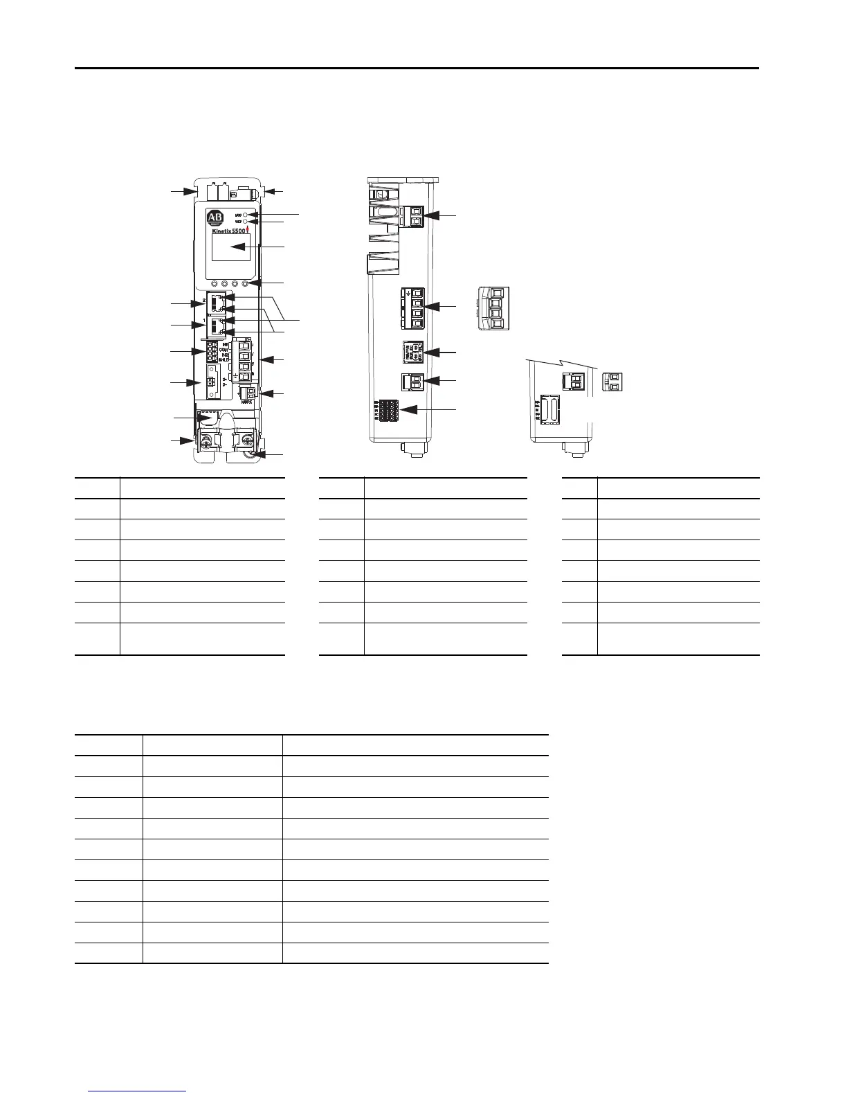
Connector Data
Use this illustration to identify the Kinetix 5500 drive features and indicators.
Kinetix 5500 Drive Features and Indicators
Kinetix 5500 Drive Connectors
Item Description Item Description Description
1 Motor cable shield clamp 8 Module status indicator 15 Motor brake (BC) connector
2 Converter kit mounting hole (under cover)
(1)
(1) Protective knock-out covers the 2198-H2DCK converter kit mounting hole. Remove knock-out for use with the converter kit.
9 Network status indicator 16 Ground terminal
3 Motor feedback (MF) connector 10 LCD display 17 Shunt resistor (RC) connector
4 Digital inputs (IOD) connector 11 Navigation push buttons 18 AC mains input power (IPD) connector
5 Ethernet (PORT1) RJ45 connector 12 Link speed status indicators 19 DC bus (DC) connector (under cover)
(2)
(2) DC bus connector ships with protective knock-out cover that can be removed for use in shared-bus configurations.
6 Ethernet (PORT2) RJ45 connector 13 Link/Activity status indicators 20 24V control input power (CP) connector
7 Zero-stack mounting tab/cutout 14 Motor power (MP) connector 21
Safe torque-off (STO) connector
(3)
(applies to only 2198-Hxxx-ERS drives)
(3) Protective knock-out cover is removed on 2198-Hxxx-ERS (hardwired STO) drives.
Designator Description Connector
IPD AC mains input power 4-position plug, terminal screws
DC DC common bus power 2-position (T-connector used in shared-bus configurations)
CP 24V control input power 2-position plug, terminal screws
RC Shunt power 2-position plug, terminal screws
MP Motor power 4-position plug, terminal screws
MF Motor feedback 2-position plug, spring terminals
BC Brake power 2-position plug, terminal screws
IOD Digital inputs 4-position plug, spring terminals
STO Safe torque off 5-position plugs, spring terminals, 2x (2 rows of 5 pins)
PORT1, PORT2 Ethernet communication ports RJ45 Ethernet
21
20
19
18
17
1
2
L3
L2
L1
1
2
+
–
1
8
3
4
13
5
6
11
10
9
12
16
7
7
U
V
W
2
1
15
14
2
1
2
Kinetix 5500 Drive, Front View
(2198-H003-ERSx drive)
Kinetix 5500 Drive, Top View
(2198-H003-ERS drive)
Kinetix 5500 Drive, Top View
(2198-Hxxx-ERS2 drive)
Protective
Knock-out
Shared-bus AC Input
Wiring Connector
Shared-bus 24V Input
Wiring Connector

 Loading...


