Rockwell Automation Publication 2198-IN001D-EN-P - February 2016 3
Kinetix 5500 Servo Drives
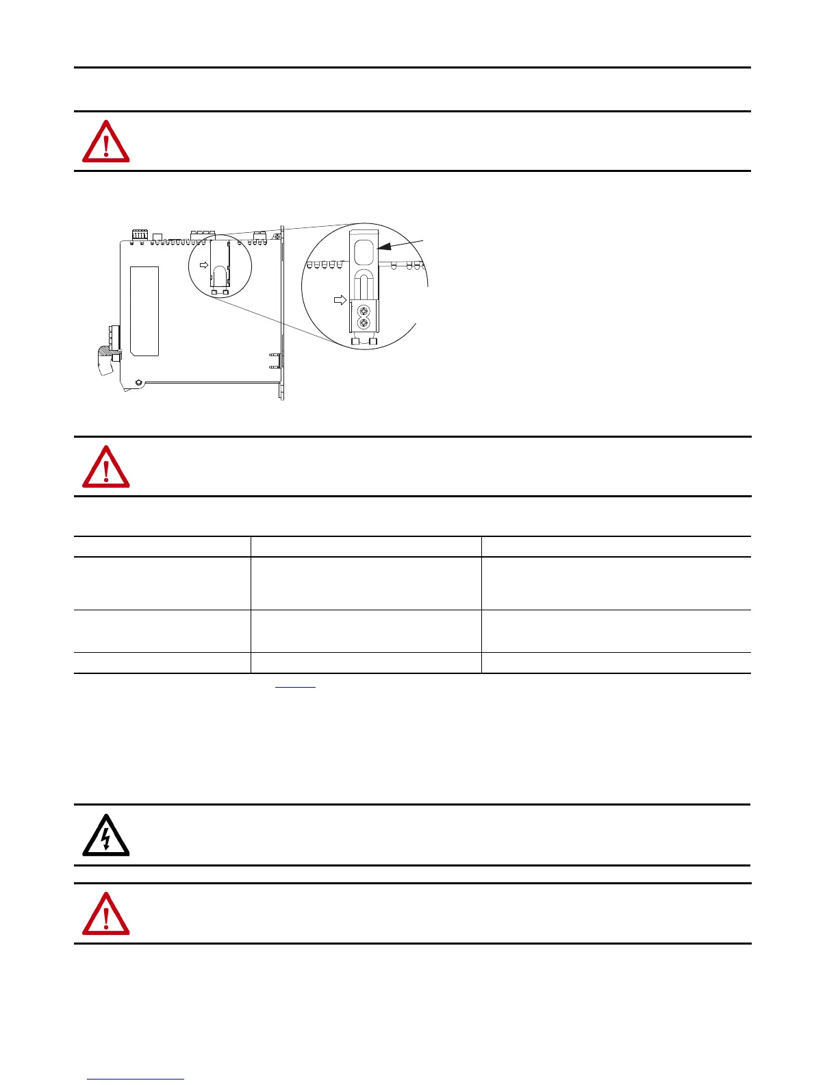
Remove the Grounding Screws
Grounding Screw Configurations
Install the Kinetix 5500 Servo Drive
These procedures assume that you have prepared your panel and understand how to bond your system. For installation instructions regarding
equipment and accessories not included here, refer to the instructions that came with those products.
ATTENTION: To avoid personal injury, the grounding screws access door must be kept closed when power is applied. If power was present and then removed,
wait at least 5 minutes for the DC-bus voltage to dissipate and verify that no DC-bus voltage exists before accessing the grounding screws.
ATTENTION: Risk of equipment damage exists. The drive ground configuration must be accurately determined. Leave the grounding screws installed for
grounded power configurations (default). Remove the screws for ungrounded, ungrounded, corner-grounded, and impedance-grounded power.
Ground Configuration
(1)
(1) Refer to the Kinetix 5500 Servo Drives User Manual, publication 2198-UM001, for example configurations.
Grounding Screw Configuration Benefits of Configuration
Grounded (wye) Both screws installed (default setting)
•UL and EMC compliance
• Reduced electrical noise
• Most stable operation
• Reduced voltage stress on components and motor bearings
• AC fed ungrounded
• Corner grounded
• Impedance grounded
Both screws removed
• Helps avoid severe equipment damage when ground faults occurs
• Reduced leakage current
Single-phase input power AC screw removed
(2)
(2) Removing the AC grounding screw to minimize leakage current in single-phase operation can affect EMC performance.
Minimizes leakage current for single-phase operation
SHOCK HAZARD: To avoid hazard of electrical shock, perform all mounting and wiring of the Kinetix 5500 drive prior to applying power. Once power is applied,
connector terminals can have voltage present even when not in use.
ATTENTION: Plan the installation of your system so that you can perform all cutting, drilling, tapping, and welding with the system removed from the enclosure.
Because the system is of the open type construction, be careful to keep any metal debris from falling into it. Metal debris or other foreign matter can become
lodged in the circuitry and result in damage to components.
Grounding screws are installed for grounded power configurations
(screws installed is default setting).
• Remove both screws for ungrounded, corner-grounded, and
impedance-grounded power for three-phase operation
• Remove only the AC screw for single-phase operation
Grounding Screw
Access Door
Kinetix 5500 Drive
(side view)
Lift door to meet
arrow at left.AC Screw
DC Screw

 Loading...


