106 Rockwell Automation Publication 750-AT006D-EN-P - January 2022
Chapter 7 Applications
changes as the pressure changes. The commanded speed is then increased or decreased as required to maintain system pressure
regardless of flow changes. When the drive is turning the pump at the required speed, the pressure is maintained in the system.
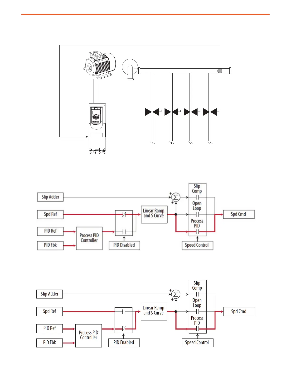
Figure 87 - Pump Application in Exclusive Mode
However, when additional valves in the system are opened and the pressure in the system drops, the PID error alters the commanded speed
to bring the process back into control. When the PID is disabled, the commanded speed is restored as the ramped speed reference.
Figure 88 - Pump When PID Is Disabled
When the PID is enabled, the speed reference is disconnected and PID output has exclusive control of the commanded speed, passing
through the linear ramp and S-curve.
Figure 89 - Pump When PID Is Enabled
Desired Pressure
9:25 [PID Ref Sel]
PID Feedback
Motor
Pump
Pressure
Transducer
 Loading...


