Rockwell Automation Publication 750-AT006D-EN-P - January 2022 105
Chapter 7 Applications
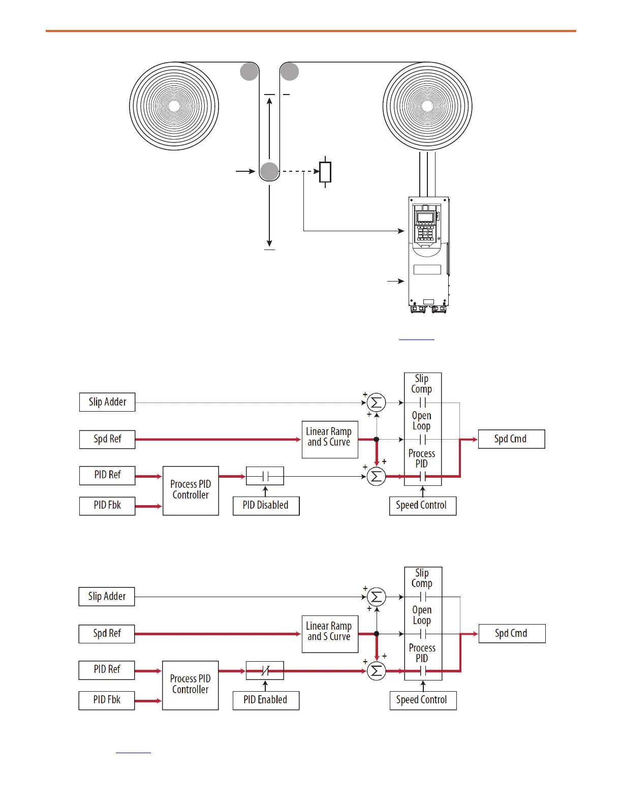
Figure 84 - Winder Application Tension Control
When the PID is disabled, the commanded speed is the ramped speed reference, as shown in Figure 85
.
Figure 85 - Winder When PID Is Disabled
When the PID is enabled, the output of the PID controller is added to the ramped speed reference.
Figure 86 - Winder When PID Is Enabled
Exclusive Mode – The output of PID controller is the speed reference in this mode, and does not trim a master speed reference. This mode
is appropriate when speed is unimportant and the only important thing is to follow the reference or setpoint. In the pumping application
example shown in Figure 87
, the setpoint is the required pressure in the system. The pressure transducer output is the PID feedback and it
Equilibrium Point
9:25 [PID Ref Sel]
Dancer Pot
9:35 [PID Fdbk Sel]
Master Speed Reference
0 Volts
10 Volts
 Loading...


