Rockwell Automation Publication 750-AT006D-EN-P - January 2022 109
Chapter 7 Applications
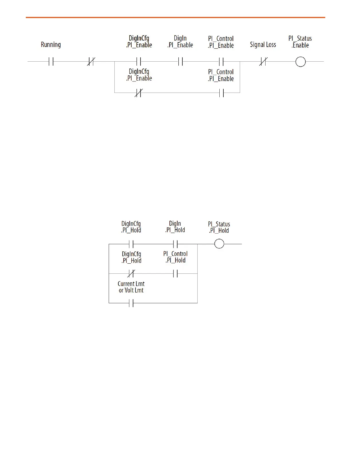
Figure 93 - PID Enable Logic
The drive must be in Run mode before the PID enabled status can turn on. The PID remains disabled when the drive is jogged. The PID is
disabled when the drive begins a ramp to stop, except when it is in Trim mode and the Stop mode bit in 9:1 [PID Cfg] is enabled.
When a digital input is configured as PI Enable, the PID enable bit of 9:2 [PID Control] must be turned on for the PID controller to become
enabled. If a digital input is not configured as PI Enable and the PID enable bit in 9:2 [PID Control] is turned on, then the PID controller can
become enabled. If the PID enable bit of 9:2 [PID Control] is left on continuously, then the PID can become enabled as soon as the drive goes
into run mode. If analog input signal loss is detected, the PID controller is disabled.
PID Hold – The process PID controller has options to hold the integrator at the present value. This option is useful in applications where part
of the process is in limit and the integrator maintains a present value to avoid windup. There are three conditions where PID hold turns on.
• If a digital input is configured to provide PID hold and that digital input is turned on, then the PID integrator stops changing. When a
digital input is configured to provide PID hold, the hold takes precedence over the PID control parameter.
• If a digital input is not configured to provide PID hold and the PID hold bit in the PID control parameter is turned on, then the PID
integrator stops changing.
• If the current limit or voltage limit is active, then the PID is put into hold.
Figure 94 - PID Hold Logic
PI Reset – This feature holds the output of the integral function at 0. The term anti-windup is often applied to similar features. It can be used
for integrator preloading during transfer and can be used to hold the integrator at 0 during Manual mode.
For example, a process can create error when the feedback signal is below the reference point. The drive increases its output frequency in
an attempt to bring the process into control. If, however, the increase in drive output does not zero the error, additional increases in output
are commanded. When the drive reaches programmed maximum frequency, it is possible that a significant amount of integral value has
been built-up (windup). This can cause undesirable and sudden operation if the system is switched to manual operation and back. Resetting
the integrator removes this windup.
Invert Error – This feature changes the sign of the error, which creates a decrease in output for increasing error and an increase in output
for decreasing error. An example of this is an HVAC system with thermostat control. In warmer weather, a rising thermostat reading
commands an increase in drive output because cold air is being blown. In colder weather, a falling thermostat commands an increase in
drive output because warm air is being blown. The PID has options to change the sign of PID error. This sign change is used when an
increase in feedback needs to cause an increase in output. The option to invert the sign of PID error is selected in the PID configuration
parameter.
PID Reference and Feedback – The selection of the source for the reference signal is entered in 9:25 [PID Ref Sel]. The selection of the
source for the feedback signal is selected in 9:35 [PID Fdbk Sel]. The reference and feedback have the same limit of possible options.
Jogging
 Loading...


