50 Rockwell Automation Publication 750-AT006D-EN-P - January 2022
Chapter 2 Product Features
This configuration can be used to compensate for compliant load mechanics by placing two poles at the anti-resonant frequency and two
zeros at the resonant frequency using the following calculations.
The following definitions are given.
J
M
= 10:900 [Motor Inertia] in units of [kg•m
2
]
R = 10:901 [Load Ratio]
F
R
= an audible resonant frequency in units of [Hz] measured by a mobile application, such as iAnalyzer Lite.
B
T
= the total mechanical friction in units of [N•m sec/rad]. This value is typically unknown and can be manually tuned. An initial value
for a 580 J motor is 0.01.
However, using the filter in this way can make the drive more sensitive to disturbances. Furthermore, the load observer is recommended to
compensate for load compliance and disturbances because it typically does a better job without having to determine these parameters.
Configured as a Second Order Lead Lag Filter
(
K > 1)
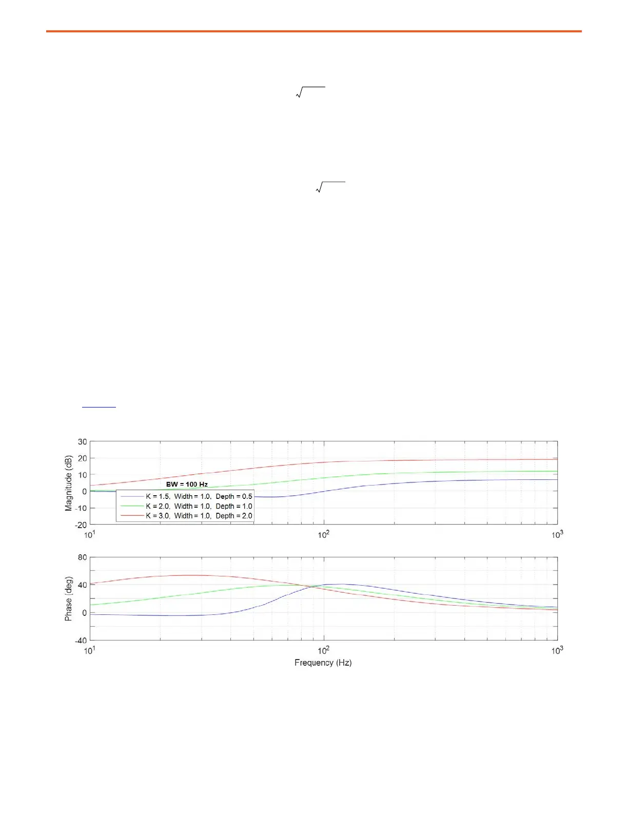
When K > 1, the notch filter is configured to operate as a second order lead-lag filter. It has two user-configurable zeros (lead) at F
D
= F/K
with damping Z
D
, and two user configurable poles (lag) at F with damping Z
W
. Bode plots with differing lead-lag filter settings for K > 1 are
shown in Figure 51
.
Figure 51 - Lead-Lag Filter Configurations
Initial recommended settings for damping are Z
W
= 1 and Z
D
= 1. Lead-lag filters have been used to boost velocity or acceleration loop
bandwidth in order to improve performance.
Z
W
B
T
4
RJ
M
F
---------------------------=
 Loading...


