Rockwell Automation Publication DRIVES-AT005D-EN-P - May 2022 31
Chapter 3 Shared DC Bus Configuration (Piggyback)
General Considerations
• All system components must be selected for the same AC-line voltage.
• A low inductance type DC bus must be used. See DC Bus Connections on page 10
for details.
• The common DC bus system may require feeder and branch circuit protection and disconnect devices. Provide appropriate circuit
protection as required by national and local electrical safety codes and regulations.
• Depending on product family and frame size, AC and/or DC fuses may be provided internally or must be supplied external to the product.
See Appendix A
and the product technical data manuals for recommended fuse information.
• PowerFlex 755T AC drives and bus supplies must not be used on undersized or high-impedance AC supply systems. The supply system kVA
must be equal to or greater than the product-related kVA, and the system impedance must be less than 10%. Operation outside these limits
can cause instability and product shutdown. You must account for the kVA of all PowerFlex 755T drives and bus supplies on the distribution
system and the system impedance of upstream transformers.
- System Impedance = (PowerFlex 755T kVA ÷ Transformer kVA) x Transformer % Impedance
• The mixture of different frame size drives in this arrangement can cause high ripple current in the smaller frame drives. In this case, place
the larger power drives physically closer to the bus supply. This placement helps current sharing among the various drives on the bus.
• The AC input power jumpers (PE-A) must be placed in the correct positions according to the power source grounding method. The PowerFlex
755TL/TR drive and all connected PowerFlex inverters must have the DC bus jumpers (PE-B) removed or set to 'out' regardless of the AC
power source grounding method. The PowerFlex 755TL/TR drives have active converters.
For recommended settings and instructions for modifying the position of the power jumpers, see the following publications:
• PowerFlex 750-Series Products with TotalFORCE® Control installation instructions, publication 750-IN100
, or PowerFlex 755TM IP00 Open
Type Kits installation instructions, publication 750-IN101.
• PowerFlex 750-Series AC Drive installation instructions, publication 750-IN001
.
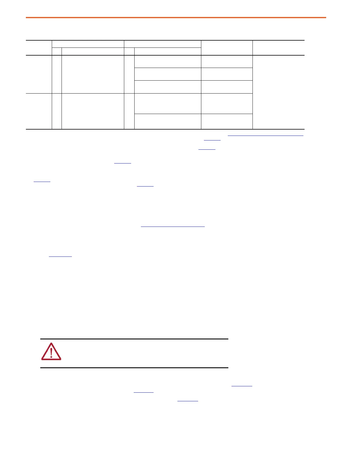
Table 2 - Compatibility Table
System
Voltage
Bus Supplies Inverter
Common Mode Core DC Bus ConditionerQty. Type Qty. Type
400/480V AC 1 PowerFlex 755TL (20G…):
Frames 5…6, 8…10
or
PowerFlex 755TR (20G…):
Frames 5…6, 8…15
n
(1)
(1) The number of inverters that can be connected can be limited by the precharge capability of the PowerFlex 755TL/TR AC drive. See DC Bus Capacitance Calculation Method on page 87
for more information about DC bus capacitor calculations and system capacitance precharging requirements. See Appendix C
for the maximum external DC bus capacitance that can
be connected.
400/480V AC PowerFlex 750-Series:
frames 2…3
1321-M048
(2)
(2) For PowerFlex 750-Series frame 2…7 drives, common mode cores are required on inverter AC output only. See Appendix B and product technical data manuals for more information.
Solid Ground
(3)
:
-P50 option NOT required,
quantity of bus conditioners
determined by the catalog
number
High Resistance Grounded
(3)
:
-P50 power option is
required, quantity of bus
conditioners determined by
the catalog number
(3) The appropriate number of bus conditioner units internal to the PowerFlex 755TL/TR AC drive are factory installed, depending on the frame size and -P50 option selection. Frames 5...6
AC drives have built in bus conditioner circuits and can’t be specified with the -P50 power option. For shipboard ungrounded power sources, a marine bus conditioner, option -P51,
might be required (contact Rockwell Automation). See Appendix B for more information about DC Bus Conditioner modules.
400/480V AC PowerFlex 750-Series:
frames 4…6
1321-M180
(2)
400/480V AC PowerFlex 750-Series:
frames 7
SK-Y1-CMCORE1
(2)
600/690V AC 1 PowerFlex 755TL (20G…):
Frames 5…6, 8…10
or
PowerFlex 755TR (20G…):
Frames 5…6, 8…15
n
(1)
600V AC PowerFlex 750-Series:
frames 3…5
(4)
(5)
(4) When 600V AC frame 3…5 inverters are used with a PowerFlex 755TL drive on 600V AC shared DC bus systems, an external DC bus voltage control method may be required to limit the
maximum routine system DC bus voltage to less than the lowest inverter DC bus overvoltage trip level. When 600V AC frame 3…5 inverters are used with a PowerFlex 755TR drive on
600V AC shared DC bus systems, the drive must be configured to limit the maximum routine system DC bus voltage to less than the lowest inverter DC bus overvoltage trip level. See
Appendix D
for more information.
(5) 600V AC frame 3…5 inverters can’t be used on 690V AC systems. See Appendix D for more information.
Fr.3: 1321-M048
(2)
Fr.4…5: 1321-M180
(2)
600/690V AC PowerFlex 750-Series:
frames 6…7
Fr.6: 1321-M180
(2)
Fr.7: SK-Y1-CMCORE1
(2)
ATTENTION: The DC bus jumpers for the PowerFlex 755TL/TR drive (PE-B),
and all connected PowerFlex inverters (PE-B), must all be set to the same
condition: all removed (out). Risk of equipment damage exists if the DC bus
power jumpers aren’t all set to the same condition.

 Loading...


