Rockwell Automation Publication DRIVES-AT005D-EN-P - May 2022 49
Chapter 5
Paralleling Two PowerFlex 755TM Regenerative Bus Supplies
System Characteristics
One PowerFlex® 755TM regenerative bus supply can be paralleled with another PowerFlex 755TM regenerative bus supply to increase the total DC
bus power rating and for applications that require system redundancy. This option is configured using the Voltage Droop feature of the PowerFlex
755TM regenerative bus supply. For more information on the Voltage Droop feature, see the PowerFlex 755T Products with TotalFORCE Reference
Manual, publication 750-RM100
.
In this configuration, both PowerFlex 755TM regenerative bus supplies would be modulating and sharing the load of the inverters connected to the
common DC bus. For redundancy applications, the PowerFlex 755TM regenerative bus supplies should be sized appropriately, such that if one bus
supply would go down, the system can operate at full capacity on a single PowerFlex 755TM regenerative bus supply.
Supported Products
At the time of publication, the following products are supported.
Typical System Configuration
This section describes typical configurations for parallel PowerFlex 755TM regenerative bus supplies. The common DC bus configuration includes
two parallel connected regenerative bus supplies as shown in Figure 13 on page 50
. In this configuration, both regenerative bus supplies are
modulating and sharing the load of the inverters connected to the common DC bus.
A dedicated isolation transformer must be used that only supplies AC power to the regenerative bus supplies. No other AC loads can be connected
to the secondary of the isolation transformer.
The PowerFlex 755T regenerative bus supply can be used with solid grounded, high-resistance grounded, and ungrounded AC power sources.
Solid-grounded and resistance-grounded power sources are recommended for typical grid-powered AC sources to improve electrical safety, ease
of ground fault detection, and to reduce unbalanced voltages. Ungrounded (floating ground) AC power sources are typically used for shipboard
isolated power systems that aren’t earth grounded. Resistance-grounded and ungrounded (floating ground) power sources may require additional
user-supplied circuits and optional bus conditioners (-P50 or -P51).
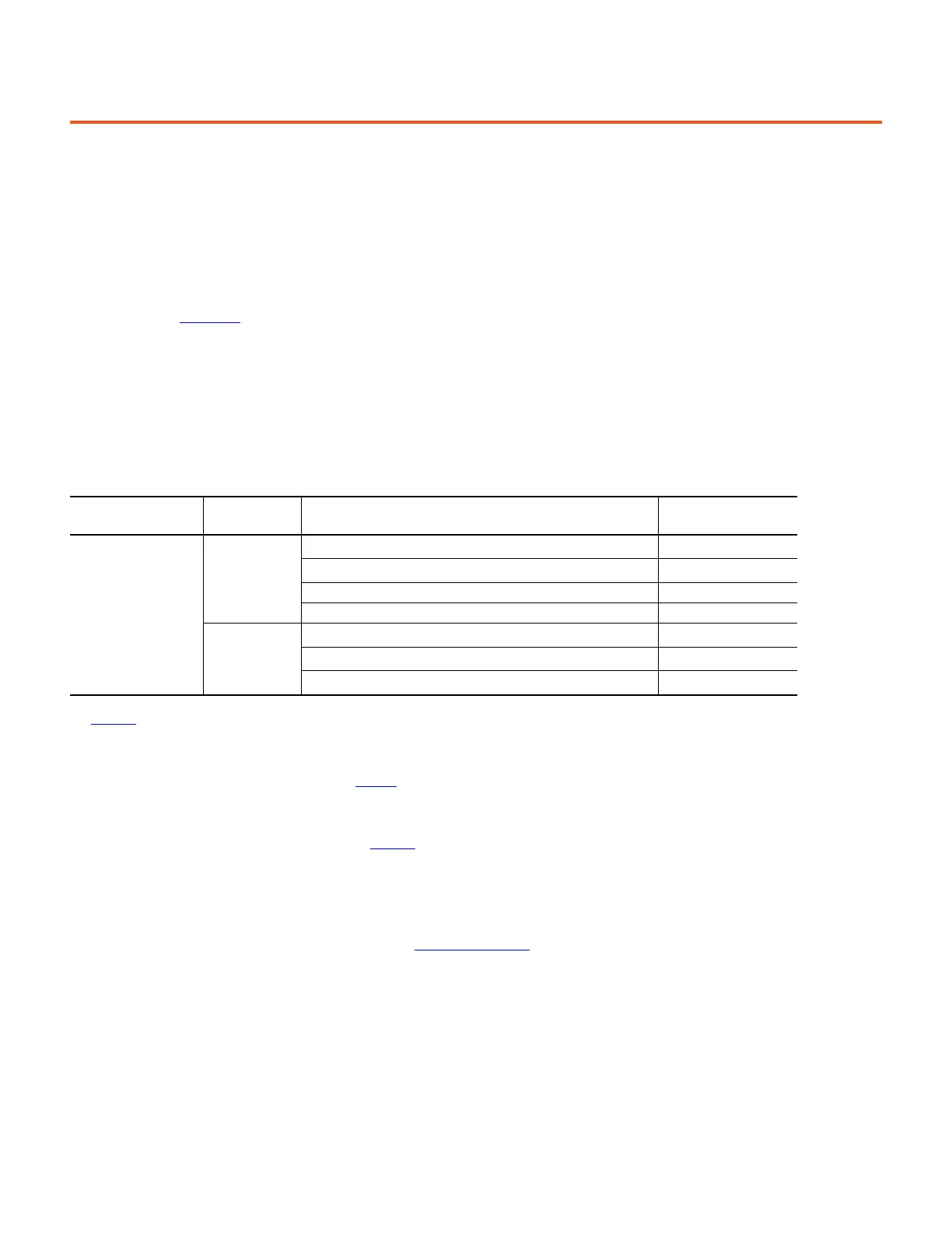
Bus Supply Products Voltage Class Supported Inverters
Inverter DC Bus
Overvoltage Trip
(1)
(1) DC bus voltage control methods may be required to limit the maximum routine system DC bus voltage to less than the lowest inverter DC bus overvoltage trip level. See
Appendix D
for more information.
PowerFlex 755TM
Regenerative Bus Supply
(20J…)
(2)
Frames 6…15
(3)
(4)
(2) PowerFlex 755TM regenerative bus supply input type (position 5 of catalog number) = 6 (frame 6…7 Regenerative and Low Harmonic AFE, 755TM Bus Supplies) or F (frame 8…15
Regenerative and Low Harmonic AFE, 755TM Bus Supplies).
(3) Only two regenerative bus supplies of the same frame size can be paralleled.
(4) PowerFlex 755T regenerative bus supply frame 6 is a panel-mounted device that requires additional external AC input power conditioning equipment. If frame 6 regenerative
bus supplies are used refer to the Installation Manual, publication 750-IN100
, for additional installation and external device information.
400/480V AC
400/480V AC PowerFlex 750-Series: frames 2…7
(5) (6)
(5) At this time, frame 1 drives aren’t recommended for use with common DC bus systems.
(6) PowerFlex 750-Series input type (position 5 of catalog number) = 1 (frames 2…4 AC input with precharge, includes DC terminals) or, 4 (frames 5…7 DC input with precharge).
815V DC
400/480V AC PowerFlex 755TM: frames 8…15
(7)
(7) PowerFlex 755TM input type (position 5 of catalog number) = D (common bus with DC precharge) or E (common bus without DC precharge). If DC input disconnect switches are
applied to inverters, you must select code 'D' common bus with DC precharge.
815V DC
Kinetix 5700 single-axis servo drives: (2198-Sxxx-ERSx) 810V DC
Kinetix 5700 dual-axis servo drives: (2198-Dxxx-ERSx) 810V DC
600/690V AC
600V AC PowerFlex 750-Series: frames 3…5
(6)
(8)
(8) 600V AC frame 3…5 inverters can’t be used on 690V AC systems. See Appendix D for more information.
1013V DC
600/690V AC PowerFlex 750-Series: frames 6…7
(6)
1162V DC
600/690V AC PowerFlex 755TM: frames 8…15
(7)
1172V DC

 Loading...


