Rockwell Automation Publication DRIVES-AT005D-EN-P - May 2022 25
Chapter 2 Regenerative Bus Supply Configuration
The resulting DC bus capacitance to output amp ratio of 35400 µF / 621.3 A RMS = 57.0 µF/A exceeds the target of 28 µF/A. No additional
capacitor banks are required.
5. Verify that the chosen PowerFlex 755TM regenerative bus supply is capable of precharging the connected inverter/drive DC bus capacitance.
• The PowerFlex 755TM regenerative bus supply maximum external capacitance data is taken from Table 16 on page 76
in Appendix A.
The total external capacitance (19900 µF) is less the PowerFlex 755TM regenerative bus supply maximum external capacitance (73002 µF).
The chosen PowerFlex 755TM regenerative bus supply is capable of precharging the connected DC bus capacitance.
The chosen PowerFlex 755TM regenerative bus supply is an acceptable solution for this common DC bus application example.
Advanced Sizing of the Regenerative Bus Supply
To perform the advanced sizing calculations, you’ll need the following system information:
•System AC source voltage
• Motor nameplate power rating
• Motor nameplate efficiency
• Product family and catalog numbers for each inverter/drive connected on the common DC bus
• Inverter/drive overload duty ratings normal duty (ND) or heavy duty (HD).
• Application power requirements and polarity for each motor during the acceleration, steady running, and deceleration phases of operation
1. Convert all motor powers to kW (kW = HP x 0.746).
2. In the following steps, PMotor is motor power required for the application, not the nameplate power of the motor (unless the application
power is unknown). If the application is absorbing power, use positive values. If the application is regenerating power, use negative values.
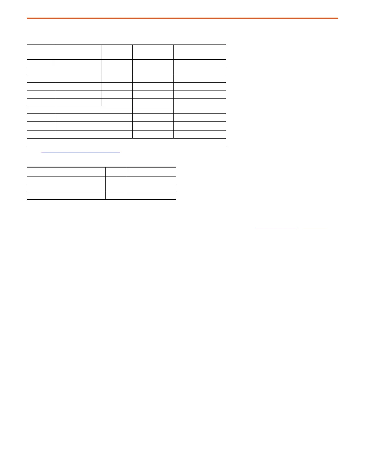
Section Name Drive Product Catalog No.
DC Bus Capacitance
(µF)
(1)
(1) See DC Bus Capacitance Calculation Method on page 87 for internal and maximum capacitance values.
Notes
Drive 1 Powerflex 755TM 20G...E242 4650 frame 8, HD
Drive 2 Powerflex 755 20G…E144 5200 frame 6, HD
Drive 3 Powerflex 755TM 20G…E295 4650 frame 8, HD
Drive 4 Powerflex 755 20G…E052 3600 frame 5, HD
Drive 5 Powerflex 755 20G…E032 1800 frame 4, HD
Bus Supply Powerflex 755TM Regen 20JxF…E760 15500 frame 9, HD
Max External Capacitance 73002
Additional Capacitance 0 µF
Total External Capacitance
(2)
(2) The calculated total external DC bus capacitance excludes the PowerFlex 755TM bus supply internal bus capacitance.
19900 µF
Total DC Bus Capacitance 35400 µF
Precharge OK
Equivalent Total Rated AC Output Amps
(1)
(1) Equivalent Total AC Output Amps is calculated by multiplying the Total Rated DC Amps * 0.9
621.3 A RMS
This System target µF/A Ratio 28 µF/A
This system calculated µF/A Ratio 57.0 µF/A
µF/A ratio OK 0 µF additional required

 Loading...


