24 Rockwell Automation Publication DRIVES-AT005D-EN-P - May 2022
Chapter 2 Regenerative Bus Supply Configuration
Example Basic Sizing of the Regenerative Bus Supply
This example represents a 600V AC input system with five motors and drives. The acceleration and deceleration times are assumed to be less than
one minute so we can take advantage of the overload duty of the inverter drives and the bus supply.
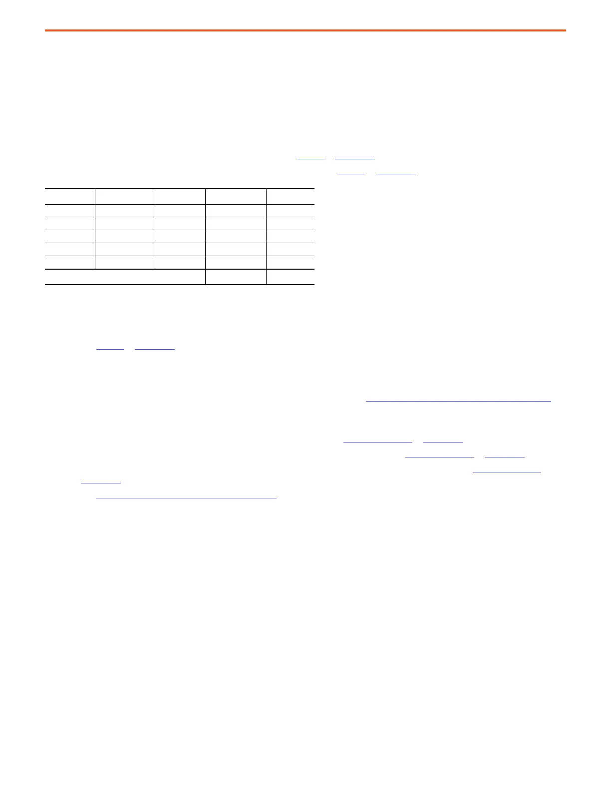
Bold text in the tables represents calculated values based on the calculation methods described earlier.
1. Use the information summarized in the following table.
• All drive products are rated for 600V AC system power voltage.
• The PowerFlex 750-Series rated DC amps data is taken from Table 14
in Appendix A.
• The PowerFlex 755TM common bus inverter DC amps data is taken from Table 15
in Appendix A.
2. The rated DC output current for the regenerative bus supply must be at least 690.3 A DC * 0.9 = 621.3 A DC heavy duty (HD).
3. The rated DC output current for the bus supply must be at least 621.3 A DC heavy duty (HD).
•Use Table 16
in Appendix A to select the PowerFlex 755TM regenerative bus supply.
The minimum DC output current rating 600V AC PowerFlex 755TM regenerative bus supply is a 20JxF…E760 frame 9 with heavy duty (HD) DC
output current rating of 710 A DC.
Verify that the system AC and DC bus bars and cables are sized to support the expected current. In this example, the total rated DC bus amps
is 621.3 A DC. The PowerFlex 755TM standard DC bus bars are rated 3000 A DC. See PowerFlex 755TM System DC Bus Ratings on page 99
for
more information about PowerFlex 755TM DC bus options and ratings.
4. Verify that the DC bus capacitance to output amps ratio meets or exceeds the target µF/A ratio.
• The PowerFlex 750-Series internal DC bus capacitance data is taken from Table 14 on page 73
in Appendix A.
• The PowerFlex 755TM common bus inverter internal DC bus capacitance data is taken from Table 15 on page 75
in Appendix A.
• The PowerFlex 755TM regenerative bus supply internal and maximum external capacitance data is taken from Table 16 on page 76
in
Appendix A.
• See DC Bus Capacitance Calculation Method on page 87
.
This example is 600V AC and has a mixture of PowerFlex 750-Series drives and PowerFlex 755TM common bus inverters. The target DC
bus capacitance to output current ratio is 28 µF/A.
Sum the internal DC bus capacitance of the inverter/drives and the bus supply. In this example, 19900 µF + 15500 µF = 35400 µF.
Sum the rated AC output current of the inverter/drives. Alternatively, use the sum of the DC bus input current and multiply this by 0.9 to
obtain an estimate of the AC output current. In this example, the DC amps from Step 2 already includes the 0.9 multiplier, so we can use
621.3 A for the equivalent total rated AC RMS output current.
Section Name Drive Product Catalog No. Rated DC Amps
(1)
(1) See Appendix A for rated DC input current values.
Notes
Drive 1 PowerFlex 755TM 20G...E242 212 frame 8, HD
Drive 2 PowerFlex 755 20G…E144 136.8 frame 6, HD
Drive 3 PowerFlex 755TM 20G…E295 267 frame 8, HD
Drive 4 PowerFlex 755 20G…E052 44.9 frame 5, HD
Drive 5 PowerFlex 755 20G…E032 29.6 frame 4, HD
Total Rated DC Amps
(2)
(2) Does not include the 0.9 multiplier for active front end DC bus voltage boost.
690.3 HD

 Loading...


