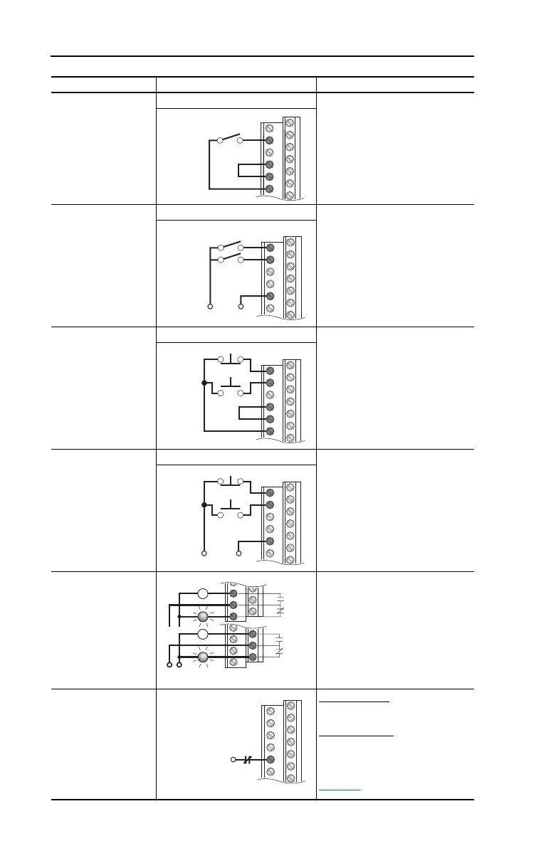
1-18 Installation/Wiring
2 Wire Control
Non-Reversing
Internal Supply Disable Digital Input 1:
Param. 361 = 0 “Not Used”
Set Digital Input 2:
Param. 362 = 7 “Run”
2 Wire Control
Reversing
External Supply Set Digital Input 1:
Param. 361 = 9 “Run Reverse”
Set Digital Input 2:
Param. 362 = 8 “Run Forward”
3 Wire Control Internal Supply Use factory default parameter
settings.
3 Wire Control External Supply Use factory default parameter
settings.
Digital Output
Form C Relays
Energized in Normal
State.
Select Source:
Param. 380, 384
Enable Input
Shown in enabled state.
Standard Control
Configure with parameter 366
Enhanced Control
Configure with parameter 366
For dedicated hardware Enable:
Remove Enable Jumper (see
page 1-15
)
Input/Output Connection Example Required Parameter Settings
2
7
8
9
Stop-Run
+24V Common
1
2
8
Run Fwd
Run Rev
1
2
7
8
9
Stop
Start
+24V Common
1
2
8
Stop
Start
11
12
13
24
25
26
Power
Source
or
NOT Fault
Fault
Run
NOT Run
6
 Loading...