10
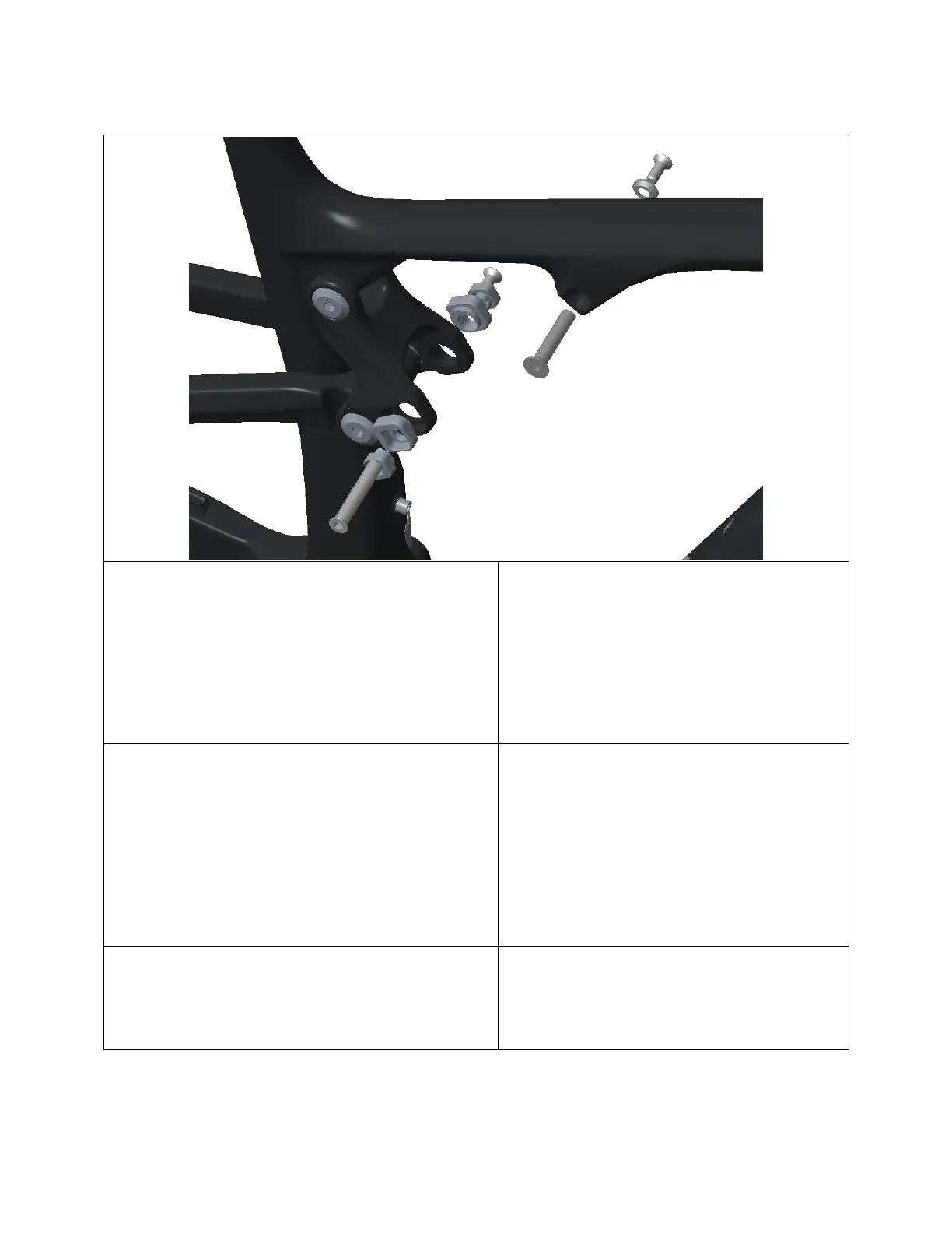
2.4 Shock Installation
1) Grease outside of Link (1807049) and FT
(1807062) Shock Bolts, as well as the
outside of Outer (1807003) and Inner
(1807004) Ride-9 Chips.
Apply Loctite 243 (blue) to M6-1.0 x
16mm (180566-016 FBY) and M6-1.0 x
12mm (180566-012 FBY) SS Screw
threads.
2) Slide shock, with correct hardware
(see exploded diagram), into front
triangle, slide in FT Shock Bolt from
the drive-side.
3) Select Ride-9 Position using the Outer
and Inner Ride-9 Chips.
4) Slide shock into link, and pass Link
Shock Bolt through Ride-9 Chips,
top link, and shock from the drive-
side.
Note: If the shock is a tight fit,
loosen the TL-SS and TL – FT Pivot
Bolts prior to inserting the shock.
Re-torque the Pivot Bolts after
installing the shock.
5) Pass M6-1.0 x 16mm SS Screw through
M6 Counter-Sunk Washer (18067064),
and thread into FT Shock Bolt.
Torque to 8 Nm.
6) Pass M6-1.0 x 12mm SS Screw
through non-drive-side Ride-9 Chip,
and thread into Link Shock Bolt.
Torque to 8 Nm.