EN
71
10.2 Command and safety device status display mode
COMMAND STATUS SAFETY DEVICE STATUS
AP PED
ORO
FT
COS BREAK
PP
CH
POWER C485 STOP/RELEASE
COMMAND STATUS:
The command status indicators on the display (segments AP = open,
PP = step mode, CH = close, PED = partial opening, ORO=clock) are
RSVQEPP]SJJ8LI]MPPYQMREXI[LIREGSQQERHMWVIGIMZIHIK[LIR
a step mode command is received, the segment PP illuminates).
SAFETY DEVICE STATUS:
8LIWEJIX]HIZMGIWXEXYWMRHMGEXSVWSRXLIHMWTPE]WIKQIRXW*8ɸ!
photocells, COS = sensing edge, BREAK= BreakAway system ACS/
BA/60 magnetic sensor or STOP/RELEASE position) are normally on.
-JERMRHMGEXSVMWSJJXLIVIPEXMZIHIZMGIMWMREPEVQWXEXISVMWRSXGSRRIGXIH8LIERMRHMGEXSVMWƽEWLMRKXLIVIPEXMZI
HIZMGILEWFIIRHMWEFPIH[MXLEWTIGMƼGTEVEQIXIV
10.3 TEST mode
8LI8)78QSHIMWYWIHXSXIWXEGXMZEXMSRSJXLIGSQQERHWERHWEJIX]HIZMGIW[MXLZMWYEPGSRƼVQEXMSR
To activate the mode, press the TEST button with the automatic barrier system at rest. If the barrier is moving, pressing
TEST stops the barrier. Pressing the button again enables TEST mode.
8LIƽEWLMRKPMKLXERHXLIFEVVMIVSTIRMRHMGEXSVPEQTMPPYQMREXIJSVSRIWIGSRH
2&*SVMRWXEPPEXMSRW[MXLX[SSTTSWMRKFEVVMIVWMJXLI8)78FYXXSRMWTVIWWIHJSVXLI70%:)FEVVMIVXLI1%78)6
barrier continues to function normally.
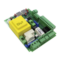
The command signal status is shown on the left hand side of the display
for 5 seconds, ONLY when the respective command signal is active (AP,
CH, PP, PE, OR).
For example, if the open command is activated, the letters AP appear on
the display.
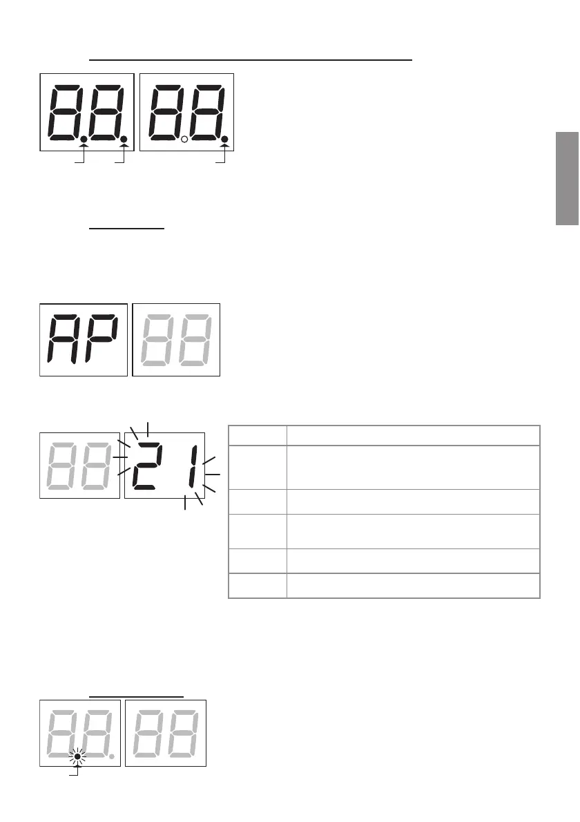
The status of the safety devices/inputs is shown on the right hand side of the display. The number of the terminal
VIPEXMZIXSXLIWEJIX]HIZMGIMREPEVQWXEXIƽEWLIW
)\EQTPI7834GSRXEGXMREPEVQWXEXI
No safety device in alarm state or barrier waiting for command.
STOP contact (N.C.) open.
Jumper the STOP contact.
Release handle or lock open.
Barrier inspection hatch open.
Sensing edge contact COS (N.C.) is open. Check connection. If
sensing edge is not installed, disable with .
Photocell contact FT (N.C.) is open (message shown on MASTER
controller displayed). Check connection. If photocell is not
installed, disable with .
EU
Shatter-proof system enabled, or not connected or incorrectly
connected.
5 (rS)
STOP contact active for MASTER barrier (message shown on
SLAVE controller displayed).
N.B.-JSRISVQSVIGSRXEGXWEVISTIRXLIFEVVMIV[MPPRIMXLIVSTIRRSVGPSWI
-JQSVIXLERSRIWEJIX]HIZMGIMWMREPEVQWXEXISRGIXLITVSFPIQVIPEXMZIXSXLIƼVWXHIZMGIMWVIWSPZIHXLIEPEVQJSV
the next device is displayed. Any further alarm states are also displayed with the same logic.
Press the TEST button again to exit test mode.
After 10 seconds with no user input, the display returns to command and safety device state display mode.
10.4 Standby mode
POWER
This mode is activated after 30 minutes with no user input. The POWER LED
ƽEWLIWWPS[P]
Press UP a, DOWN b, + or - to reactivate the control unit.