EN
74
COM
COM
+24V
+ES
+LAM
COM
COM
LNA
LNB
+SC
10 11 12 13 14 15 16 17 18 19 20
+LUCI
COM
COM
+24V
+ES
+LAM
COM
COM
LNA
LNB
+SC
10 11 12 13 14 15 16 17 18 19 20
+LUCI
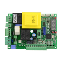
MASTER
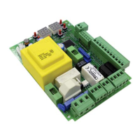
SLAVE
• Unlock the barrier.
AGILIK-KB-BIONIK4HP-BIONIK6-BIONIK8. Turn the key anticlockwise by two full turns.
BIONIK4. Open the release cover.
• The barrier goes to 45° degree.
• After a few seconds, the message 3+$6 is shown on the display. The controller unit launches a calibration procedure.
The operating parameters of the motor are determined during calibration.
• If the motor calibration procedure is successful, the message 3+$ƽEWLIWSRXLIHMWTPE]
• To lock the barrier again
AGILIK-KB-BIONIK4HP-BIONIK6-BIONIK8. Turn the key clockwise by two full turns.
BIONIK4. Close the release cover and turn the key.
• The acquisition procedure now starts. The message $XWR is shown on the display and the barrier starts opening
at low speed.
• 3RGIXLIFEVVMIVSTIRQIGLERMGEPWXSTMWVIEGLIHXLIFEVVMIVWXSTWFVMIƽ]8LIQIWWEKI$XWRƽEWLIWSRXLIHMWTPE]
• The barrier closes until it reaches the barrier closed mechanical stop.
If the acquisition procedure is completed successfully, the display enters the command and safety device state display mode.
-JXLIJSPPS[MRKIVVSVQIWWEKIWEVIWLS[RSRXLIHMWTPE]VITIEXXLIEGUYMWMXMSRTVSGIHYVI
• QR3+GEPMFVEXMSRTVSGIHYVIJEMPIH
• $33.(EGUYMWMXMSRIVVSV
For more information, see chapter 16 “Alarms and faults”.
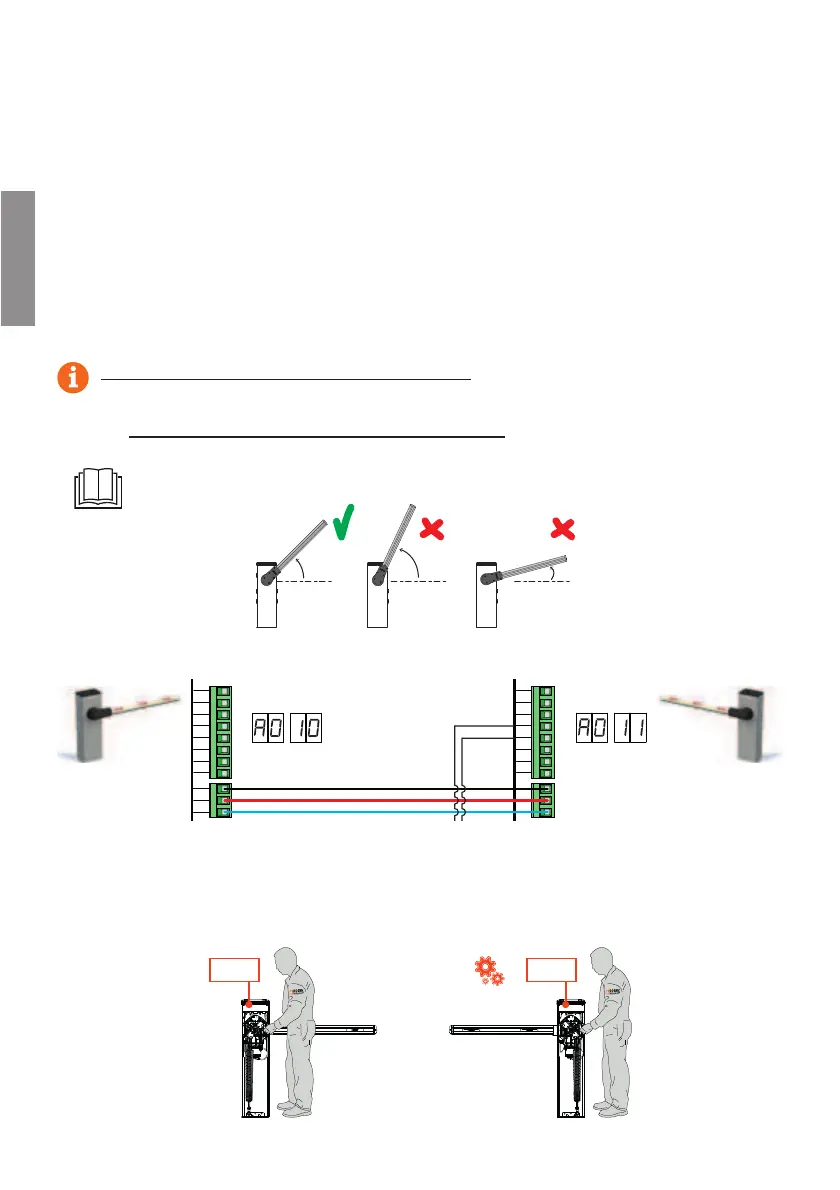
11.3 MASTER/SLAVE acquisition procedure:
1. Check the spring balance setting and the mechanical stop settings.
For further information, refer to the installation manual of the barrier.
45°
>45°
<45°
2. With both control units not powered (and with battery disconnected, if present), make the bus connections on the
1%78)6ERH70%:)GSRXVSPYRMXWWIIƼK
3. Enable RS485 serial communication (MASTER)$
4. Enable RS485 serial communication (SLAVE)$
5. Select the position of the barrier in relation to the gate, using parameter. The factory setting of the parameter is
with the barrier installed on the right () and the boom opening/closure gate on the left (seen from the inspection
hatch side). The position of the SLAVE barrier is automatically set to complementary.
IMPOSTAZIONE DI FABBRICA
FACTORY SETTING