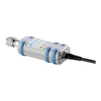
PC control R&S NRP-Z11/21/31/41/61/211/221
1137.7470.12 1.4 E-8
Operation via the R&S NRP-Z4 passive USB adapter
Fig. 1-2 is a schematic of the measurement setup. The order in which the cables are connected is not
critical.
Fig. 1-2 Configuration with Passive USB Adapter R&S NRP-Z4
Connecting the sensor to the DUT
See Table 1-1 for the type of male RF connector a certain power sensor has and which female
connectors it mates with. Using light pressure, and keeping the male connector perpendicular, insert it
into the female connector and tighten the locking nut (right-hand thread). In many cases, the RF
connector only requires manual tightening. However, for maximal measurement accuracy, the RF
connector must be tightened using a torque wrench with a nominal torque that corresponds with the
tightening torque shown in Table 1-1.
Operation via the Active USB Adapter R&S NRP-Z3
Fig. 1-3 shows the configuration with the Active USB Adapter R&S NRP-Z3, which also makes it
possible to feed in a trigger signal for the Timeslot and Trace modes. The order in which the cables are
connected is not critical.
Fig. 1-3 Configuration with Active USB Adapter R&S NRP-Z3

 Loading...