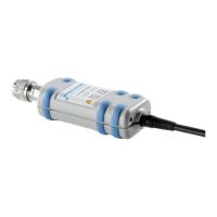
PC control R&S NRP-Z11/21/31/41/61/211/221
1137.7470.12 1.6 E-8
As an alternative to the supplied external power supply, power can also be supplied using a DC voltage
source with an output voltage of 12 V to 24 V and a power output of at least 24 W. Make sure that the
polarity is correct (positive pole inside, negative pole outside). The alternative DC voltage source must
be in the same building as the R&S NRP-Z5 and must be connected to the latter via a cable with a
maximum length of 30 m. Power must not be supplied from a low-voltage supply system.
The supplied external power supply is short-circuit-proof and is also protected by an internal fuse. It is
not possible to change the fuse or open the unit.
The external power supply is not intended for outdoor use.
Keep within the temperature range of 0°C to 50°C.
If there is any condensation on the external power supply, dry it off before connecting it
to the AC supply.
Ports and LEDs
The power sensors are connected to the front panel of the R&S NRP-Z5. The ports and LEDs on the
front panel of the R&S NRP-Z5 are shown in Fig. 1-5.
Sockets for connecting the power sensors
Green LEDs for indicating normal operation
Yellow LEDs for indicating faults
Fig. 1-5 Ports and LEDs on front panel
On the rear panel are the ports for power supply, USB host, trigger input and trigger output. The ports
on the rear panel are shown in Fig. 1-6.
Trigger output (BNC socket)
Trigger input (BNC socket)
Built-in plug allowing connection to Rohde & Schwarz measuring instruments (via R&S NRP-
Z2) or to a PC (via R&S NRP-Z4)
USB socket (type B) for connection to the USB host (PC or Rohde & Schwarz measuring
instrument without sensor socket)
Power supply socket (supplied external power supply unit or alternative power supply (12 V to
24 V/24 W))

 Loading...