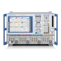
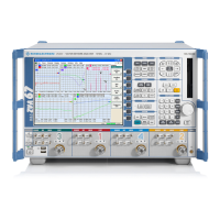
R&S ZVB Instrument Construction and Function Description
1145.1078.82 3.83 E-4
Testing the Network Controller Board
Testing the IF inputs
It is assumed that there is one functioning reflectometer in the instrument.
Disconnect the IF-MEAS and IF-REF cable from each of the reflectometers.
Connect the input to be tested at the end of the appropriate IF cable (W136, W137, W138, W139,
and W146, W147, W148, W149) to a functioning port using the adapter cable and SMA-N adapter .
Set the R&S ZVB to CW sweep mode, CENTER 17.512345 MHz.
Setting at the port used for the measurement: POWER -10 dBm
Setting at the port associated with the network controller under test: WAVE QUANTITY ax or bx.
Enter service function 2.21.2.18.17512345 (IF = 17.512345 MHz).
Disable level corrections with SF 2.21[..24].2.15.1
If the level displayed on the R&S ZVB's screen is not within the range -4 dBm ± 2 dB, the board must
be replaced.

 Loading...


