13
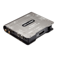
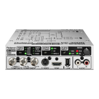
Front Panel
1 2 3 4
For information on what the colors and the lighted and ashing states of the indicators mean,
refer to “Indicator Colors/Operation” (p. 16).
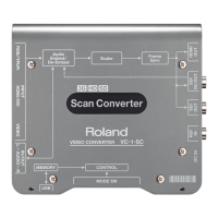
1. RGB/YPbPr INPUT connector/indicator
Connect RGB signals from a computer, analog-component signals from a video camera, or other
such equipment.
2. HDMI/DVI INPUT connector/indicator
Connect a video camera or other HDMI source equipment.
You can also input DVI-D signals from a computer by using a conversion cable.
3. VIDEO INPUT jack/indicator
Connect composite signals from a video camera or other such equipment.
4. AUDIO IN/OUT jacks/indicator
Connect video-camera audio signals or the like.
You can switch between input (embedding) and output (de-embedding) by operating mode
switch 1 (MODE SW 1; p. 25).
Panel Descriptions
 Loading...