25
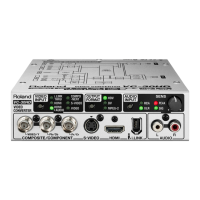
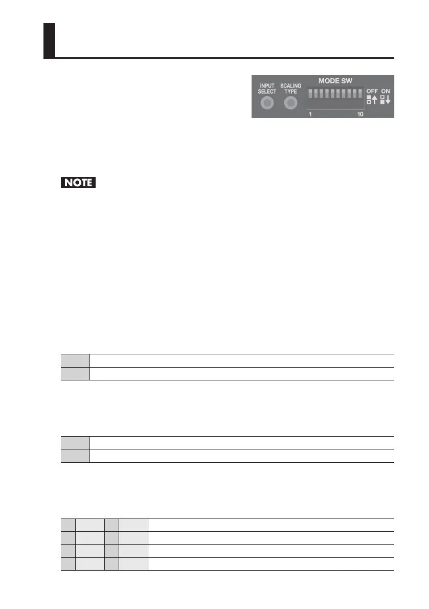
Use the mode switches (MODE SW) on the side panel
to set the operation mode of the VC-1-SC. By default,
only switch 10 is set to “ON.” Before making any
setting changes, rst set switch 10 to “OFF.”
INPUT SELECT switch
Each press switches the input connector as shown below.
Auto g SDI IN g HDMI/DVI IN g RGB/YPbPr IN g VIDEO IN g Auto g
* The indicator for the currently selected connector ashes or lights up steadily.
When the Auto setting has been made, the SDI IN/OUT connector is locked to operation as input
connector. Use as output connector is not possible. Also, when the Auto setting is in eect, never
make simultaneous connections to multiple input connectors.
SCALING TYPE switch
Each press changes the screen aspect (scaling) as shown below.
Full (full-screen output, regardless of dierences in input and output aspect)
g Letterbox (black borders inserted according to dierences in input and output aspect)
g Cropped (parts of the screen cut o according to dierences in input and output aspect)
g Dot by dot (output as-is, with no scaling performed)
g Full g
MODE SW 1
This species audio input and output (embedding/de-embedding).
OFF Audio jacks are used for input (embedding).
ON Audio jacks are used for output (de-embedding).
MODE SW 2
This species the groups for embedding/de-embedding the SDI audio.
OFF 8 channels of Group 1 and Group 2
ON 8 channels of Group 3 and Group 4
MODE SW 3/4
These specify the channels for embedding/de-embedding the audio.
3 OFF 4 OFF Channels 1 and 2
3 ON 4 OFF Channels 3 and 4
3 OFF 4 ON Channels 5 and 6
3 ON 4 ON Channels 7 and 8
Setting the Operation Mode
 Loading...