Panel Descriptions
14
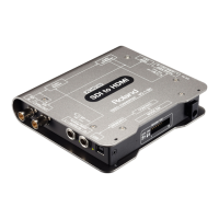
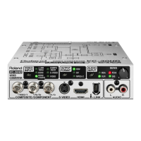
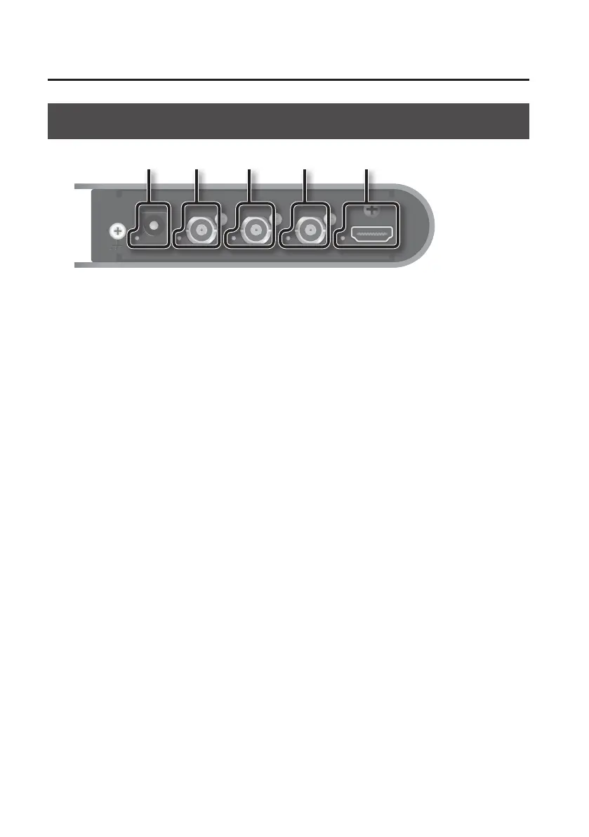
Rear Panel
1 2 3 4 5
1. DC IN jack/indicator
Connect the included AC Adaptor. The indicator lights up when the VC-1-SC is receiving power.
2. REF IN connector/indicator
Connect a clock source device for synchronization.
* It is possible to use this unit as a frame synchronizer when supported sync signal is input.
3. SDI OUT connector/indicator
Connect a video deck, monitor, or other SDI input equipment.
4. SDI IN/OUT connector/indicator
This functions as input when SDI input has been selected and as output at other times.
When using this for input, connect a video camera or other SDI source equipment.
When using this for output, connect a video deck, monitor, or other SDI input equipment.
5. HDMI OUT connector/indicator
Connect a TV monitor or other HDMI input equipment.
 Loading...