Quick Start Guide
13
August 2012
Step 3: Set mode switch and switching time delay
1. Select “Dry on” or “Wet on” mode.
2. Select 0.3, 1, 3, 10, or 30 seconds for the delay before switching output state.
Note
There is a five second delay when changing mode or time delay
The small cut-out in the rotating switch indicates time delay and mode
Recommended installation for a high level alarm is “Dry on” and for a low level alarm it is
“Wet on”. Do not install in the normally ‘off’ state
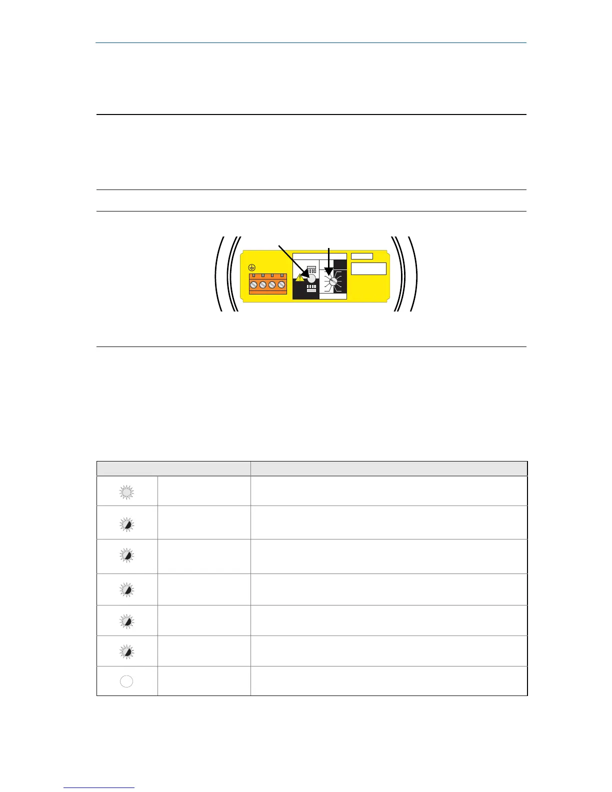
Figure 8. Top-down view of example cassette inside the housing
A. LED
B. Mode Switch and Time Delay
LED indication
When the LED is red and flashing, it indicates the 2120 may be uncalibrated,
successfully calibrated, has an electrical load problem, or has an internal PCB fault.
See Table 1 for further information.
Table 1. LED flash rate
LED Flash Rate Switch Status
Continuous Output state is on
1 every second Output state is off
1 every 2 seconds Uncalibrated
1
1. Refer to the “Replacement and Calibration of Electronic Cassettes” section in the 2120 Reference Manual
(00809-0100-4030) or Manual Supplement (00809-0200-4030).
1 every 4 seconds Load fault; load current too high; load short circuit
2 times every second Indication of successful calibration
3 times every second Internal PCB fault (microprocessor, ROM, or RAM)
Off Problem (e.g. supply)