August 2012
8
Quick Start Guide
Step 2: Electrical installation
Before use, check that suitable cable glands and blanking plugs are fitted and
fully tightened.
Isolate supply before connecting the switch or removing the electronics.
The functional earth terminal must be connected to an external
earthing system.
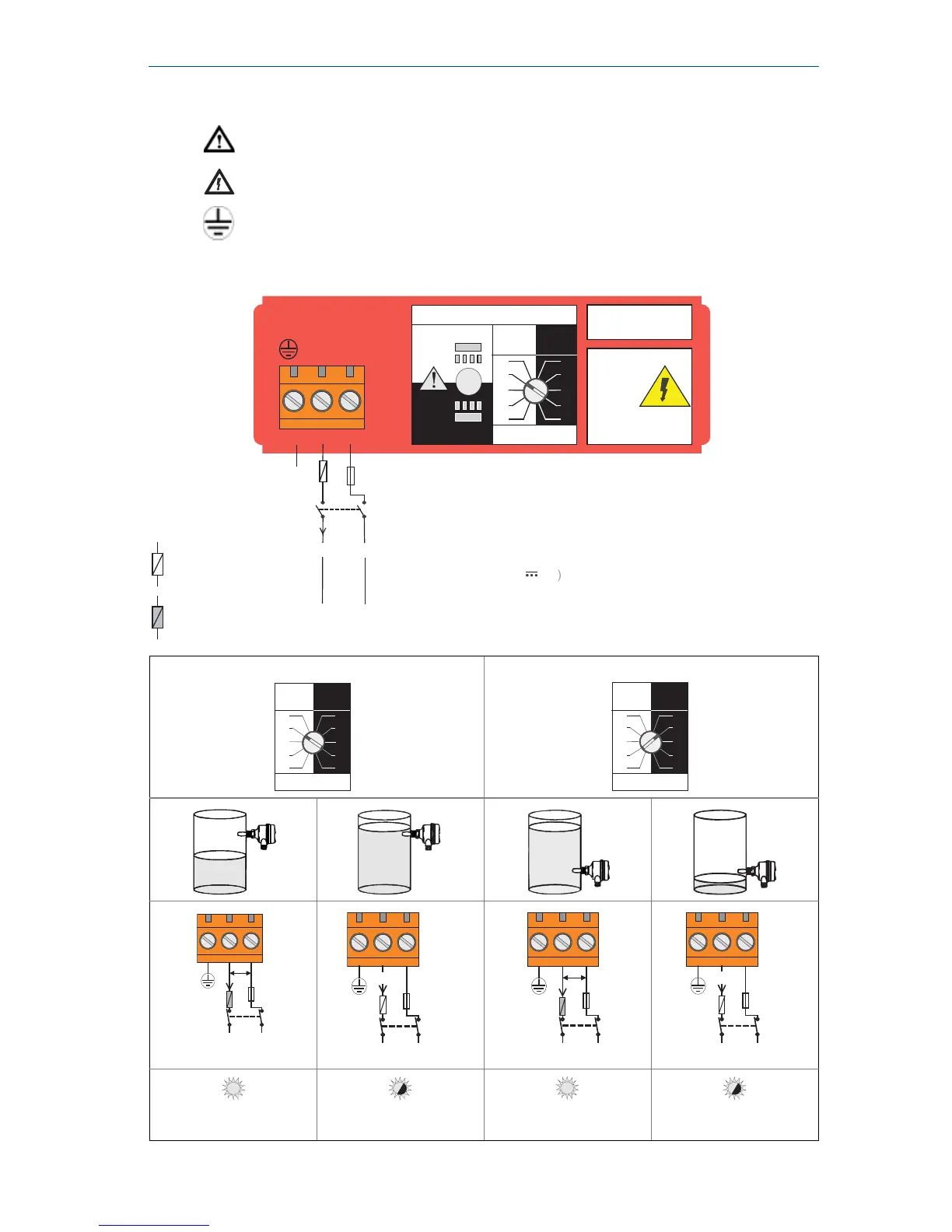
Direct load switching electronics cassette (two-wire, red label)
High level Dry = ON Low level Wet = ON
LED on continuously
LED flashes each
second
LED on continuously
LED flashes each
second
Direct Load
Switching
WARNING
Isolate Supply
Before Removing
OPERATION MODE
Dry On Mode
Dry
Wet
Wet On Mode
Dry
Wet
Dry On Wet On
Seconds Delay
0.3 0.3
3
30
10
1
3
30
10
1
123
LINE
LOAD
PE
(Ground)
Neutral
Live
0V
Fuse 2A(T)
R
I
L
R = External load (must be fitted )
U = 20 - 264V ~ (ac) (50/60Hz)
I
OFF
< 4
mA
I
L
=
20 -
500
mA
U = 20 - 60 V (dc