January 2017
8
Quick Start Guide
3. Apply a small amount of process-compatible lubricant applied to the tube
cone to help prevent galling and facilitate sealing. Insert the tubing into the
connection and tighten finger tight.
4. Tighten the gland nut to a torque of 25 ft-lb.
Note
A weep hole has been designed into the transmitter for safety and leak detection. If fluid
begins to leak from the weep hole, isolate the process pressure, disconnect the
transmitter, and reseal until the leak is resolved.
2.2 Consider housing rotation
To improve field access to wiring or to better view the optional LCD display:
1. Loosen the housing rotation set screw using a
5
/64-in. hex wrench.
2. Turn the housing left or right maximum up to 180° from its original
position.
(1)
Note
Over rotating can damage the transmitter.
3. Re-tighten the housing rotation set screw to no more than 7 in-lb when
desired location is reached.
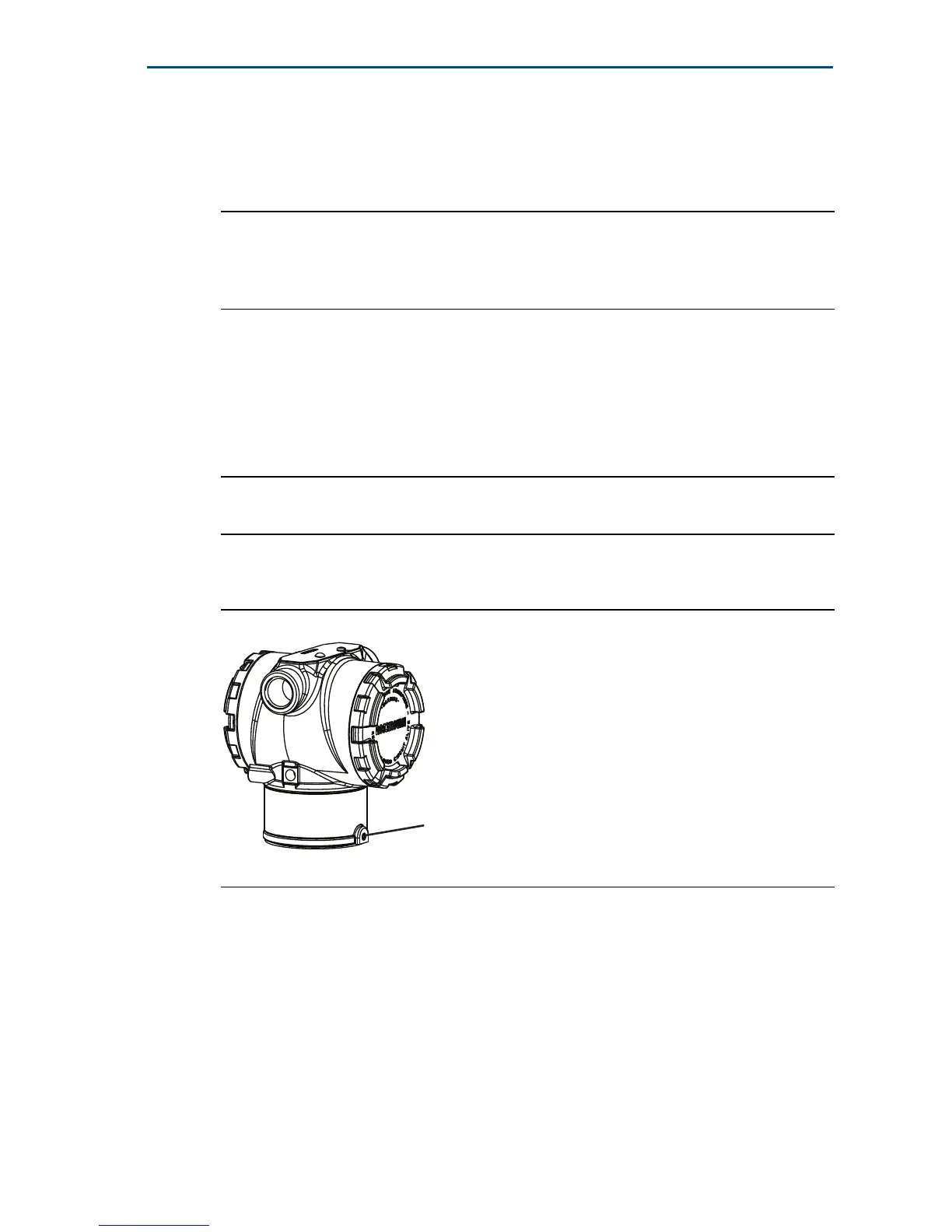
Figure 4. Transmitter Housing Set Screw
A. Housing rotation set screw (
5
/64-in.)
2.3 Set the switches
Set alarm and security switch configuration before installation as shown in
Figure 5.
The alarm switch sets the analog output alarm to high or low.
- Default alarm is high.
The security switch allows (unlocked symbol) or prevents (locked symbol)
any configuration of the transmitter.
- Default security is off (unlocked symbol).
1. Rosemount 3051C original position aligns with “H” side; Rosemount 3051T original position is the opposite side of
bracket holes.