Quick Installation Guide
00825-0100-4663, Rev BC
December 2012
Rosemount 8732
12
Wafer Sensors
Gaskets
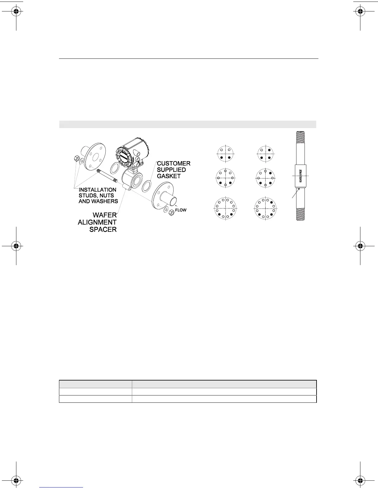
The sensor requires a gasket at each of its connections to adjacent devices or piping. The
gasket material selected must be compatible with the process fluid and operating conditions.
Metallic or spiral-wound gaskets can damage the liner. Gaskets are required on each side of
a grounding ring. See Figure 8 below.
Alignment
1. On 1.5 through 8-inch (40 through 200 mm) line sizes. Rosemount strongly recommends
installing the alignment spacers provided to insure proper centering of the wafer sensor
between the process flanges. Sensor sizes of 0.15, 0.30, 0.5 and 1 in. (4 through 25
mm), do not require alignment spacers.
2. Insert studs for the bottom side of the sensor between the pipe flanges and center the
alignment spacer in the middle of the stud. See Figure 8 for the bolt hole locations
recommended for the spacers provided. Stud specifications are listed in Table 3.
3. Place the sensor between the flanges. Make sure that the alignment spacers are
properly centered on the studs. For vertical flow installations slide the oring over the stud
to keep the spacer in place. See Figure 8. To ensure the spacers match the flange size
and class rating for the process flanges see Table 4.
4. Insert the remaining studs, washers, and nuts.
5. Tighten to the torque specifications shown in Table 5. Do not overtighten the bolts or the
liner may be damaged.
Table 3. Stud Specifications
NOTE
Sensor sizes of 0.15, 0.30, and 0.5 in. mount between AMSE 1/2-inch flanges. Using carbon
steel bolts on sensor sizes of 0.15, 0.30, 0.5 and 1 in. (15 and 25 mm), rather than the
required stainless steel bolts, will degrade the flow sensor measurement.
Figure 8. Wafer gasket placement
Nominal Sensor Size Stud Specifications
0.15 – 1 inch (4 – 25 mm) 316 SST ASTM A193, Grade B8M Class 1 threaded mounted studs
1.5 – 8 inch (40 – 200 mm) CS, ASTM A193, Grade B7, threaded mounting studs
Spacer Installation
Horizontal meters
Vertical meters
O-ring
4663RevBCQIG.fm Page 12 Thursday, January 10, 2013 5:33 PM