Quick Installation Guide
00825-0100-4663, Rev BC
December 2012
Rosemount 8732
20
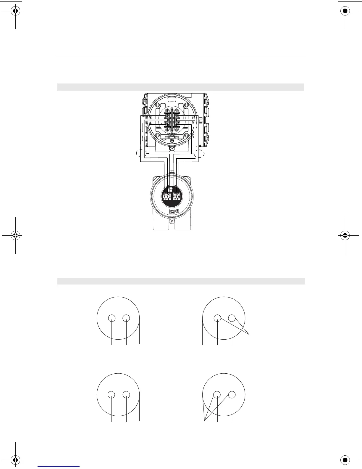
NOTE
When using the Rosemount supplied combination cable, the signal wires for terminals 18
and 19 contain an additional shield wire. These two shield wires should be tied with the main
shield wire at terminal 17 at the sensor terminal block and cut back to the insulation in the
transmitter junction box. See Figure 17.
Figure 16. Remote Mount Wiring Diagram
Figure 17. Combination Coil and Signal Cable Wiring Diagram
Transsmiter
Tube
Coil Drive Cable
1 Red 2 Green 3 Shield 17 Shield 18 Black 19 White
Cut Shield
Signal Cable
17 Shield 18 Black 19 White1 Red 2 Green 3 Shield
4663RevBCQIG.fm Page 20 Thursday, January 10, 2013 5:33 PM