Quick Installation Guide
00825-0100-4663, Rev BC
December 2012
Rosemount 8732
21
Integral Mount Transmitters
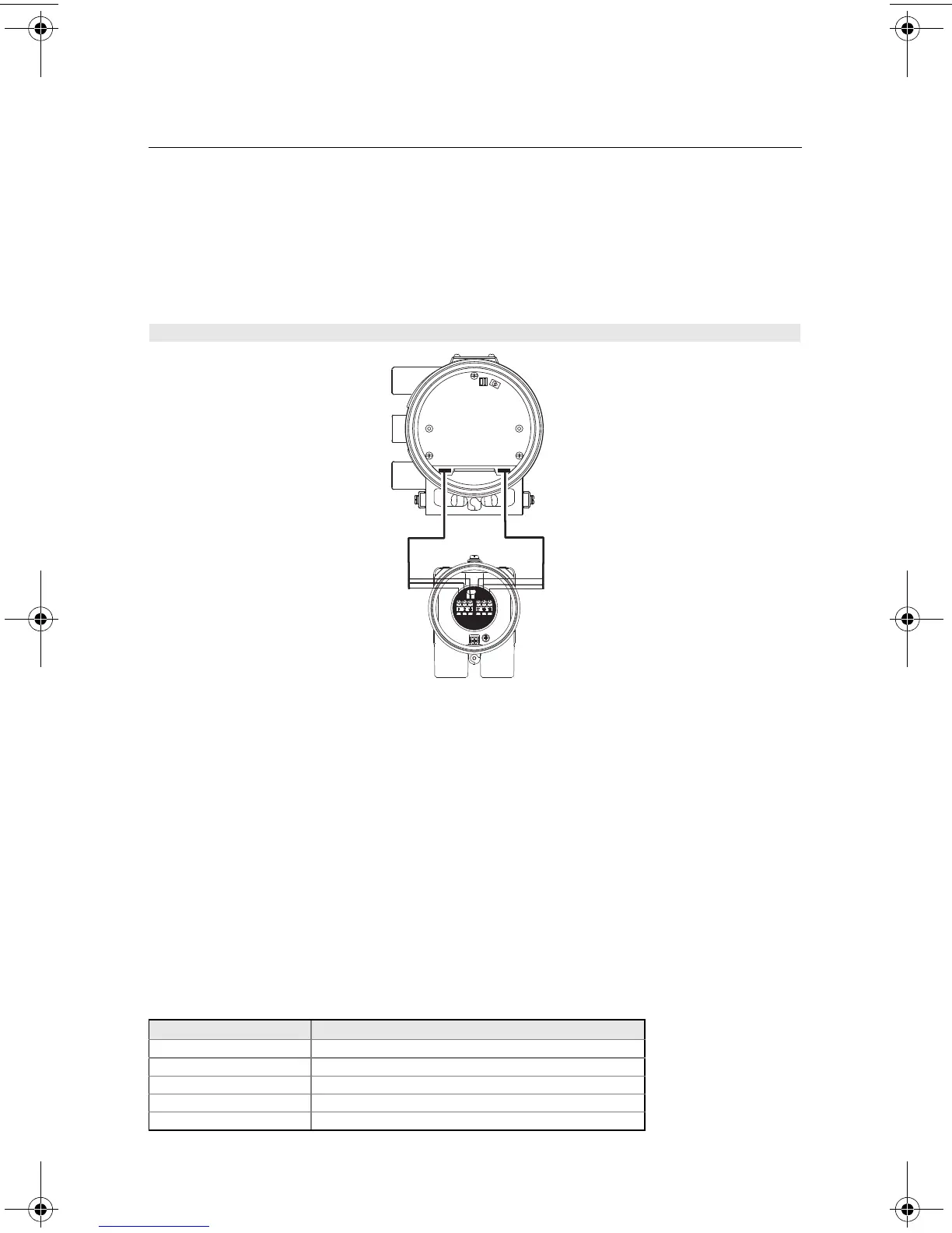
The interconnecting wire harness for an integral mount transmitter is installed at the factory.
See Figure 18. Do not use cable other than that supplied by Emerson Process
Management, Rosemount, Inc.
FOUNDATION Fieldbus Connection Wiring
Transmitter Communication Input
The F
OUNDATION fieldbus communication requires a minimum of 9 V dc and a maximum of
32 V dc at the transmitter communication terminals. Do not exceed 32 V dc at the
transmitter communication terminals. Do not apply ac line voltage to the transmitter
communication terminals. Improper supply voltage can damage the transmitter.
Field Wiring
Power independent of the transmitter power supply must be supplied for F
OUNDATION
fieldbus communications. Use shielded, twisted pair for best results. In order to get
maximum performance in new applications, twisted pair cable specifically designed for
fieldbus communications should be used. The number of devices on a fieldbus segment is
limited by the power supply voltage, the resistance of the cable, and the amount of current
drawn by each device. See Table 10 for cable specifications.
Table 10. Ideal Cable Specifications for Fieldbus Wiring
Figure 18. 8732EST Integral Mount Wiring Diagram
Characteristic Ideal Specification
Impedance 100 Ohms ± 20% at 31.25 kHz
Wire Size 18 AWG (0,8 mm
2
)
Shield Coverage 90%
Attenuation 3 db/km
Capacitive Unbalance 2 nF/km
4663RevBCQIG.fm Page 21 Thursday, January 10, 2013 5:33 PM