18 • Hardware Overview ULTRIX-FR12 Installation Guide (v4.0)
1. PSU Connections
There are four power input modules located on the back of the ULTRIX-FR12. Each input module
includes four power connectors that correspond to the four connectors on an Ultripower power
supply.
2. Frame Reference Module
This module provides two (individual or looping) HD-BNC inputs that accept reference signals
supporting the following reference types: analog black, tri-level sync, and AES/DARs. The REF A
port is the primary reference port.
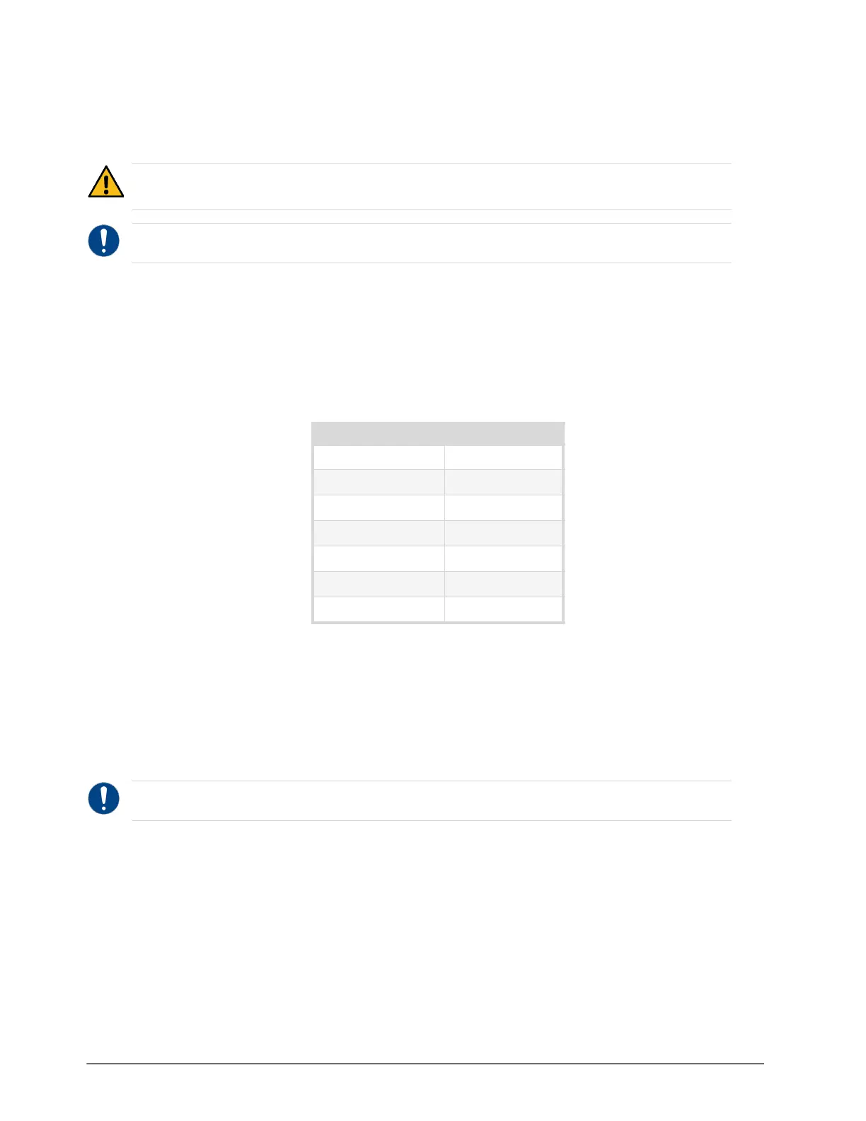
Refer to Table 5 to learn what REF ports are supported on each type of blade.
3. Frame Control Module
This module provides the following connections.
› Each Ethernet port is an RJ45 connector used to connect the router to an external 1Gbe
Ethernet network. Each port has its RJ45 connector wired as a Network Interface Card (NIC).
Connect ENET1 as the primary ethernet connection to bridge the external Ethernet network to
the local communications bus for monitoring and control of the router. Only connect ENET2
when a redundant connection is required.
› USB 3.0 Type A Port — This port provides the ability for various USB-serial converts to be
attached for serial communications with the ULTRIX-FR12 router. Refer to “Supported
USB-Serial Converters”.
› Micro SD Card — The Micro SD card provides system storage and a default software build. Do
not remove this card unless directed by Ross Technical Support.
› ALARM Connector — This 3-pin connector provides a hard-wired alarm output. An output is
triggered on this port when the ULTRIX-FR12 detects a configured alarm. Refer to “Cabling the
ALARM Port”.
The LTC and R-OUT ports are not implemented.
Caution — The ULTRIX-FR12 requires a minimum of two Ultripower units and has a specific power up
process. Refer to '“Powering the ULTRIX-FR12”.
Notice — Always connect one Ultripower unit to one ULTRIX-FR12 power input module.
Table 5
Blades — Supported REF Ports
Blade ULTRIX-FR12
SDPE-ACUITY REF A
SDPE-CARBONITE REF A or REF B
ULTRIX-HDX-IO REF A or REF B
ULTRIX-IP-IO REF A or REF B
ULTRIX-IPX-IO REF A or REF B
ULTRIX-MODX-IO REF A or REF B
ULTRIX-SFP-IO REF A or REF B
Notice — The Ethernet ports do not provide Power-over-Ethernet (PoE).