36 • Cabling Your Router ULTRIX-FR12 Installation Guide (v4.0)
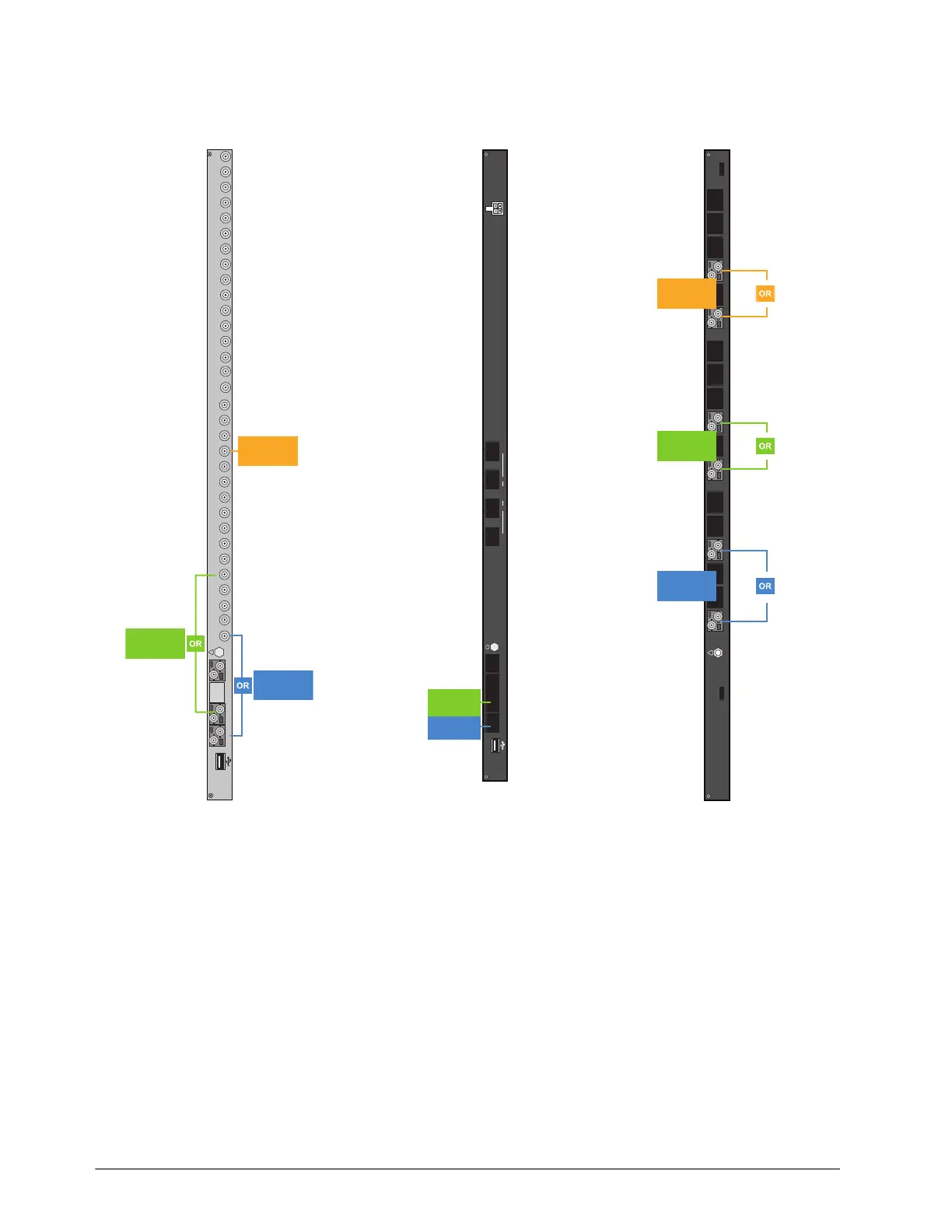
Figure 7, Figure 8, and Figure 9 illustrate the output connections allocated for UltriScape Heads on
each type of I/O blade.
To cable ports for an UltriScape Head
1. If your blade requires an HD-BNC connection:
a. Connect the end of a 75ohm coaxial cable with an HD-BNC connector on one end to an OUT
HD-BNC on the ULTRIX-FR12 rear panel.
b. Connect the other end of the coaxial cable to the device that displays the UltriScape Head
from that OUT HD-BNC on the router.
2. If your blade requires a fiber optic connection, refer to “Connecting the SFP Ports”.
3. Make a note of the port you have chosen for the UltriScape Head as this information is needed
when you configure the UltriScape Head settings in DashBoard.
Figure 7 UltriScape Heads —
Ultrix-HDX-IO
Figure 8 UltriScape Heads —
ULTRIX-IPX-IO
Figure 9 UltriScape Heads —
ULTRIX-SFP-IO
C DA B
Ultrix HDX-IO
!
9 10111213141516
OUT
56781324
9 10111213141516
IN
56783214
UltriScape
Head 3
UltriScape
Head 1
UltriScape
Head 2
Ultrix IPX-IO
CDAB
!
1
324100G
UltriScape
Head 1
UltriScape
Head 2
Ultrix-SFP-IO
AUX A AUX B 1 2 3 4 5678910 11 12 13 14 15 16
!
UltriScape
Head 3
UltriScape
Head 1
UltriScape
Head 2