List of Figures
AC-225x Series Hardware Installation Manual v
List of Figures
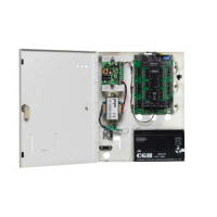
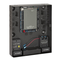
Figure 1: AC-225x Panel ................................................................................. 9
Figure 2: Sample AC-225x Configuration...................................................... 13
Figure 3: Inputs Wiring – Non-supervised Inputs ........................................... 14
Figure 4: Door Lock – Failed Close ................................................................ 15
Figure 5: Door Lock – Failed Open ................................................................ 16
Figure 6: Wiring Between PS-33 and AC-225x .............................................. 17
Figure 7: AC-225x Wiring Communications .................................................. 17
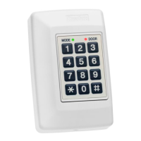
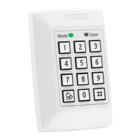
Figure 8: Reader Wiring ................................................................................ 18
Figure 9: Connector Location for MD-IO84 or MD-D02 ................................. 19
Figure 10: Normally Open Input Connection ................................................. 21
Figure 11: Normally Closed Input Connection ............................................... 21
Figure 12: Normally Open Supervised Input (Single Resistor) .......................... 22
Figure 13: Normally Open Supervised Input (Double Resistor) ........................ 23
Figure 14: Normally Closed Supervised Input (Single Resistor) ........................ 23
Figure 15: Normally Closed Supervised Input (Double Resistor) ...................... 24
Figure 16: DIP Switch ................................................................................... 30
Figure 17: DIP Switch with Baud Rate Setting ............................................... 31
Figure 18: DIP Switch for Door Setting .......................................................... 31
Figure 19: DIP Switch with Internal Network Address Setting ........................ 31
Figure 20: Daisy Chaining ............................................................................. 34
Figure 21: MD-N32 Configuration Connecting a Single Panel ....................... 35
Figure 22: Connecting Multiple Access Control Panels with MD-N32 ............ 36
Figure 23: Connecting Multiple Access Control Panels with AC-225x ............ 36
Figure 24: Remote Site Modem Configuration .............................................. 36
 Loading...