Installation
AY-T6350 Installation and Programming Manual 11
7. Insert the unit’s cable wire into the cable hole and wire the unit
as described in Section 3.2.
8. Screw the back cover to its mounting location.
9. Carefully re-attach the front cover of the unit.
10. Secure the front cover by using the supplied security Torx screw.
A Torx security screw tool is provided to tighten the security Torx
screw.
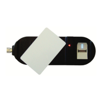
The reader can also be mounted using strong epoxy glue. After
application, the reader should be firmly held in place until the
glue dries.
3.2 Wiring
The reader is supplied with an 18” pigtail, comprising six wires.
To connect the reader to the controller:
1. Prepare the unit's cable by cutting the cable jacket back 3.2 cm
(1¼”) and stripping the wire 1.3 cm (½”).
2. Prepare the controller cable by cutting the cable jacket back 3.2
cm (1¼”) and stripping the wire 1.3 cm (½”).
3. Splice the reader’s pigtail wires to the corresponding controller
wires (as listed in Table 1) and cover each joint with insulating
tape.
Table 1: Wiring Colors
Reader Color Function
5~16 VDC Red +DC input
Shield/Ground Black Ground
Data 1 White Data 1
Data 0 Green Data 0
LEDCTL Brown LED/buzzer control
Tamper Purple Tamper
 Loading...