ROTAX 125 MAX evo, Junior MAX evo, Mini MAX evo, Micro MAX evo
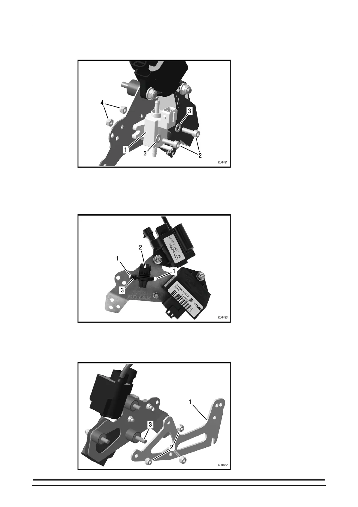
Magnetventil (Pos. 1) mit Zyl. Schrauben M5 (Pos. 2), Beilagscheiben (Pos. 3) und
Sicherungsmuttern M5 (Pos. 4) auf die Trägerplatte montieren (nur zutreffend für
MAX evo).
Bild 16
Bei den Modellen Junior MAX evo, Mini MAX evo und Micro MAX evo werden die
Bohrungen (Pos. 1) für die Montage der Blindstecker (TNr. 666900) (Pos. 2)
verwendet und mit Kabelbinder (Pos. 3) gesichert.
Hinweis: Blindstecker (TNr. 666900) ist nicht im Lieferumfang enthalten, jedoch als Ersatzteil
erhältlich.
Bild 17
Trägerplatte MAX (Pos. 1) in korrekte Position bringen und mit Sicherungsmuttern
M6 (Pos. 2) auf die Rundpuffer (Pos. 3) der Trägerplatte montieren.
Hinweis: Ein Gewinde der Rundpuffer muss länger sein, um das Massekabel zu montieren.
Hinweis: Die Verwendung von Scheiben ist nicht notwendig.
Bild 18
Seite/Page 14/55
Ausgabe/Edition 07/2016
 Loading...


