10
FA ROTEX A1 BGe - 02/2014
4 x Set-up and installation
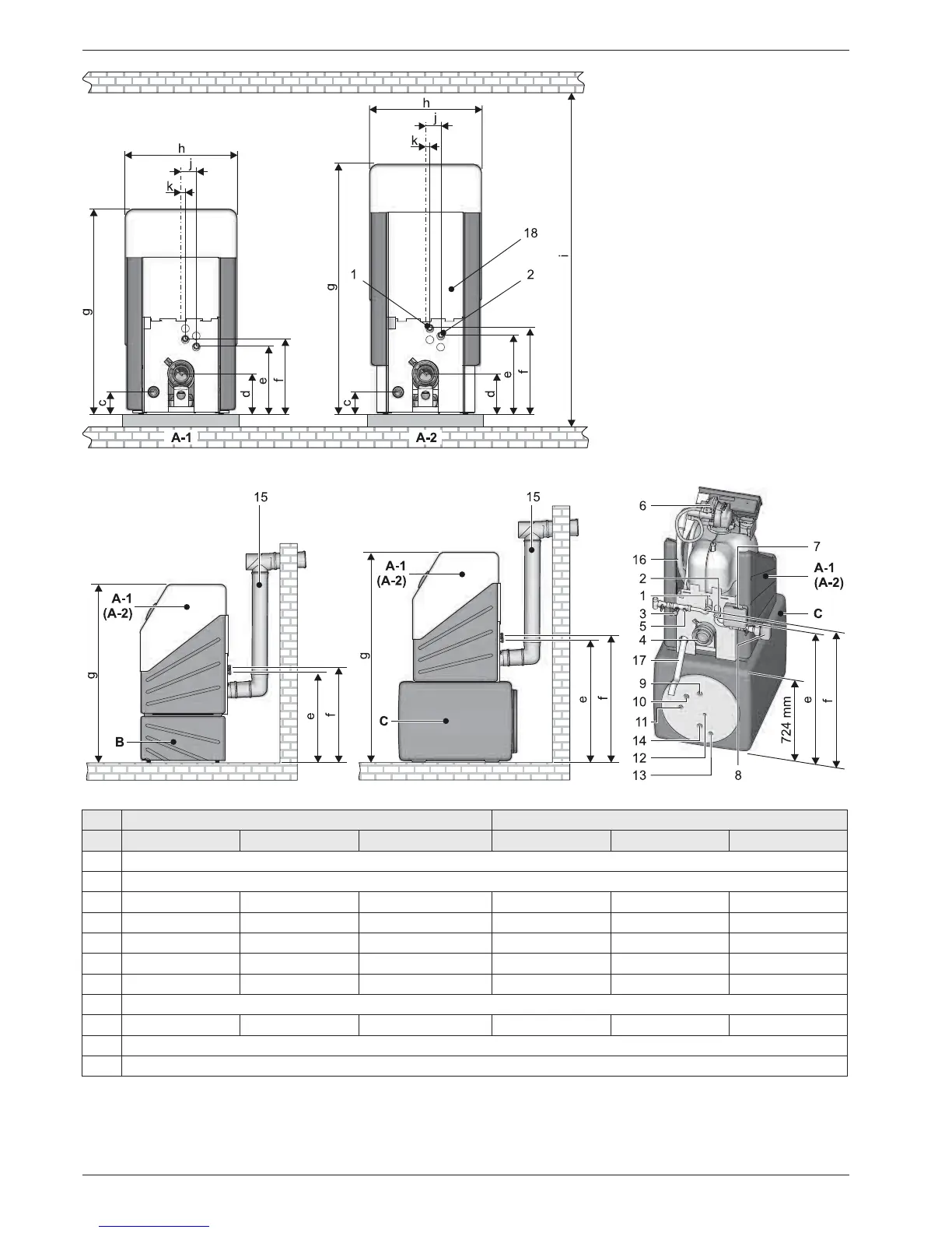
Tab. 4-2 Installation dimensions A1 BG in mm
Fig. 4-2 Dimensions and connection dimensions - view from the rear (for legend see tab. 4-1)
Fig. 4-3 Dimensions and connection dimensions with boiler frame and sub-tank (for legend see tab. 4-1)
A1 BG 25(F)-e A1 BG 40(F)-e
Dim. on the floor on the sub-tank on underframe on the floor on the sub-tank on underframe
a 400
b720
c 135
±15
785
±15
500
±15
135
±15
785
±15
500
±15
d 230
±15
880
±15
590
±15
230
±15
880
±15
590
±15
e 365
±15
1000
±15
755
±15
425
±15
1065
±15
815
±15
f 405
±15
1045
±15
795
±15
465
±15
1105
±15
855
±15
g 1100 1730 1480 1340 1970 1720
h625
i 1340 1890 1650 1590 2140 1890
j85
±15
k25
±15