4 x Set-up and installation
FA ROTEX A1 BGe - 02/2014
15
Flue gas system resistance
To ensure safe burner start-up and stable setting values, a
minimum resistance is required in the flue gas line, particularly
with liquid gas units. If this is not achieved you need to fit a si-
lencer (E8 MSD, 15 45 78 or E11 MSD, 15 45 79).
– With the hot water storage tank connected and activated stor-
age tank temperature sensor, the ROTEX A1 initially switches
into storage charging mode after the burner starts. In this
mode, the burner blower runs with max. speed.
– If there is no hot water storage tank connected, the resistance
of the flue gas system with completely open heat distribution
valves in "Manual Operation" (see chapter 10.5 or documen-
tation "ROTEX RoCon BF Controller") or in the setting "Full
Load" for the emission measurement (see chapter 15.2)
needs to be determined.
Ɣ Measure the resistance with the differential measurement unit
on the flue gas measurement point between the flue gas and
intake air measurement openings (differential pressure for the
A1 BG 25(F)-e at 0.5 mbar, for the A1 BG 40(F)-e at least
1 mbar).
Tab. 4-3 shows the maximum permissible height of the flue gas
line for the case that the ROTEX A1 is operated in the nominal
output range.
1) Cross section of the shaft: 135 mm x 135 mm
2) Cross section of the shaft: 160 mm x 160 mm
Tab. 4-3 Maximum permitted height of the flue gas pipe in m (when
operating in the nominal output range)
Any restriction on the output range may require a recalculation of
the maximum permitted height for the flue gas pipe. The charac-
teristics for the flue gas calculation can be obtained from fig. 4-6
and chapter 15 "For the chimney sweep".
The flue gas mass flow of the systems depends on the burner
output set.
4.5.2 Connecting the flue gas line to the ROTEX A1
Requirements
– The flue system fulfils the requirements described in
section 4.5.1.
– The flue system fulfils any other required national or regional
safety requirements.
– The ROTEX A1 is installed correctly.
Connection
Ɣ Connect ROTEX A1 to the flue gas system within the place of
installation (for pipe dimensions, see fig. 4-2 or fig. 4-7).
Ɣ Place the nameplate of the flue gas pipe in the installation
room.
Tab. 4-4 Connection dimensions for LAS connection to the ROTEX A1
Set-up
version
(ref. fig. 4-4)
A1 BG 25(F)-e A1 BG 40(F)-e A1 BG 40(F)-e
DN 80 DN 80 DN 110
123
1)
8
1)
22
2)
222
1)
17
1)
40
2)
322
1)
17
1)
25
2)
4211417
52210 -
62210 -
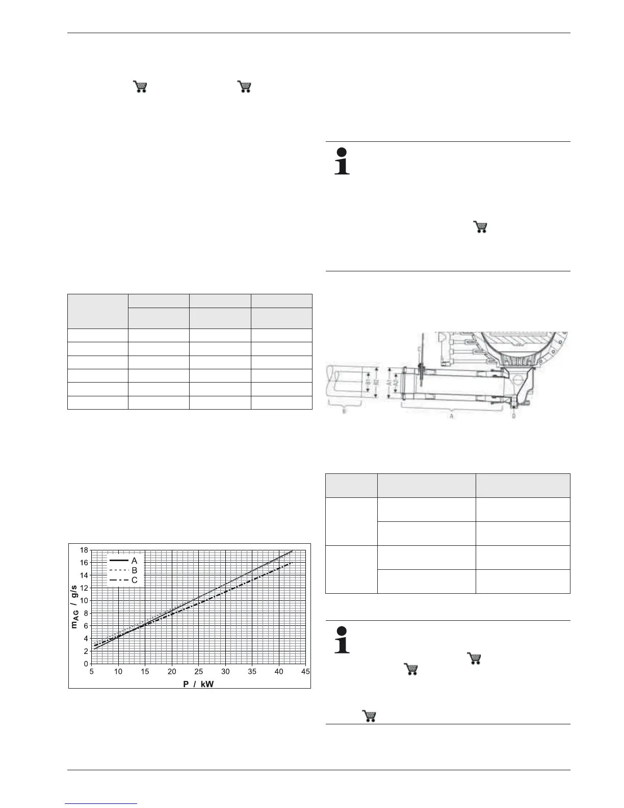
A Natural gas E, H
B Natural gas L, LL
C Fluid gas (propane, butane)
m
AG
Flue gas mass flow in g/s
P Burner load in kW
Fig. 4-6 Flue gas mass flow in relation to the burner output
Basically, any flue gas line that complies with the
minimum requirements according to the EN 14471 and
that has the CE-labelling can be connected
(see section 4.5.1).
Each flue gas line must be installed with a suitable test
adapter for checking and setting the combustion
values. The ROTEX LAS construction sets each in-
clude a test adapter (D8 PA, 15 50 79.00 93).
We recommend the use of the associated ROTEX flue
gas set (see fig. 4-8). They satisfy all requirements and
are also fitted with special acid-proof seals.
A Boiler connection
B Flue gas connection
C Flue gas temperature sensor
D Connection for condensate
drain
Fig. 4-7 Connection dimensions for LAS connection to the ROTEX A1
Connection
side
Connection Connection
dimension in mm
A Boiler side A1 Flue gas DN 80
Collar
Inside diameter
= 80.4
+0.8
A2 Supply air DN 125
Collar
Inside diameter
= 127.0
–0.5
B Flue gas
side
B1 Flue gas DN 80 Outside diameter
= 80.0
+0.3
B2 Supply air DN 125 Outside diameter
= 126.0
±0.3
In some cases, the resonance in the flue system can
amplify the noise at the mouth of the flue gas pipe. The
noise level can be effectively reduced with the applica-
tion of a silencer (E8 MSD, 15 45 78 bzw.
E11 MSD, 15 45 79).
Air suction noises are generated during ambient air-
dependent operation. The noise level can be effectively
reduced with the application of a silencer (G ZLSD,
15 45 77).