8 x Hydraulic connection
FA ROTEX A1 BGe - 02/2014
43
8.2 Hydraulic system connection
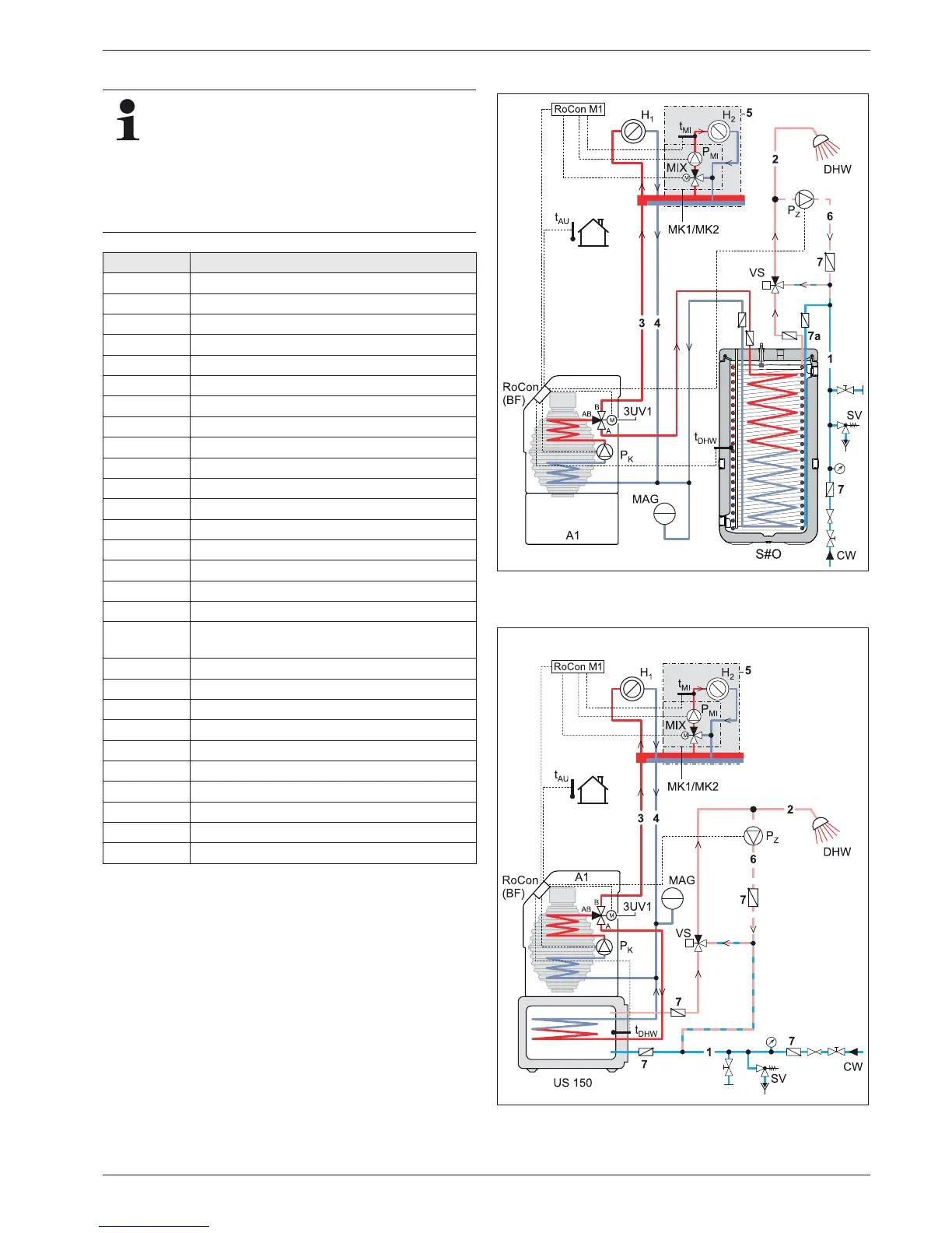
Fig. 8-5 and fig. 8-6 show examples of the integration
of a Sanicube INOX hot water storage tank and a sub-
tank US 150. Note that the hydraulic circuit shown does
not claim to be complete and your system planning
must therefore still be carried out thoroughly.
As a ROTEX certified company you will find other ex-
amples for hydraulic system connection concepts on
the ROTEX Homepage.
Short name Meaning
1 Cold water distribution network
2 Hot water distribution network
3 Heating inflow
4 Heating return flow
5 Mixer circuit
6 Circulation
7 Check valve, return valve
7a Non return valves
3UV1 3-way switch valve (DHW)
A1 A1 oil or gas condensing boiler
CW Cold water
DHW Domestic hot water
S#O Hot water storage tank SC 538/16/0
H
1,
H
2
... H
m
Heating circuits
MAG Diaphragm expansion vessel
MIX 3-way-mixer with drive motor
MK1 Mixer group with high-efficiency pump
MK2
Mixer group with high-efficiency pump (PWM
controlled)
P
K
Boiler circuit pump
P
Mi
Mixing circuit pump
P
Z
Circulation pump
RoCon BF A1 condensing boiler
RoCon M1 Mixer circuit control
SV Safety overpressure valve
t
AU
Outside temperature sensor
t
DHW
Storage tank temperature sensor (RoCon OT1)
t
Mi
Mixer circuit flow temperature sensor
VS Burns guard VTA32
Tab. 8-1 Abbreviations on hydraulics plans
Fig. 8-5 Standard connection schematic ROTEX A1 with Sanicube (for
legend see tab. 8-1)
Fig. 8-6 Standard connection schematic ROTEX A1 with US 150
(for legend see tab. 8-1)