12 x Technical data
FA ROTEX A1 BGe - 02/2014
57
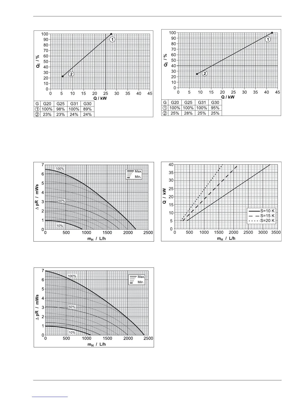
12.4 Performance diagrams
12.5 Flow rate and residual feed height
Q Burner load in kW
Q
i
Relative burner load in %
G Gas type (test gas)
(1) Maximum permissible burn-
er load
(2) Minimum permissible burner
load
Fig. 12-2 Permissible burner load of the ROTEX A1 BG 25(F)-e
Fig. 12-3 Permissible burner load of the ROTEX A1 BG 40(F)-e (legend
see
fig. 12-2
Δ
p
R
Remaining pumping height
m
H
Flow heating network
Fig. 12-4 Residual conveying height A1 BG 25(F)-e
Δ
p
R
Remaining pumping height
m
H
Flow heating network
Fig. 12-5 Residual conveying height A1 BG 40(F)-e
Q Heating output
m
H
Flow heating network
S Spread (t
V
- t
R
)
Fig. 12-6 Required throughput volumes dependent on the heating out-
put and the design temperature spread